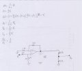
I identified the basic op amps in the figure, but don't know what type of op amp is the one circled in green. Could someone please help me finish this problem?
You may have mislabeled some components. The two components circled in green are resistors. The triangle is the op amp. It is probably an ideal one, so it has no real-world counterpart.
The resistors circled in green form a simple voltage divider. So the voltage presented to the +ve op-amp terminal V+, is related to Vi by V+=(1/3)*Vi. You can assume this is the case because an ideal op-amp would have zero bias current into the input terminals.
From the +ve terminal to the op-amp output terminal the circuit is a non-inverting stage with the output voltage given by (1+4/2)*V+.
Between the op-amp output terminal and the output point (node Vo) there is another voltage divider with divider factor 5/10=0.5
You have three circuits there. V1 goes into voltage divider, result is V1'. V1' goes into non-inverting amplifier, result is Vo'. Vo' goes into voltage divider, result Vo. Do the math. I get ½.
I want to give some general notices/ideas about op-amp without going in deep details in equations.
So op-amp always tries to bring the voltage difference in its inputs to 0:
prov:
As ideal opamp has infinite gain, hence out =A(inpls - inmns), so as A is infinite and out is constant => (inpls - inmns) should equal to 0 => inpls = inmns
Based on this principle you can understand all the above brought schemes.

 Facebook
 Google
 GitHub
 Linkedin