Two Switch Forward converter with transient spikes on gate to source voltage

Thread Starter

PowerSayan

Joined Oct 21, 2023
9
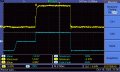
Good day everyone, so I have a problem with my two switch forward converter. As soon as the current increases at the input from around 200mA a transient/spike starts appears at both the turn-on and turn-off of Vgs. The higher I go and push it the bigger the spikes ultimately get, which is problematic as I need to get up to around 2A and 323V at the input.

I've tried increasing Rg from 10 ohm I used to 82 ohms now and it did help a bit, haven't tried higher as its already quite high. I have a diode conducting back over Rg and a 10kOhm pull down resistor. I am using a HCPL 3120 as my gate driver. Adding a DC link capacitor very close to the switches did help take away some ringing after the spike.

In the image Vgs (Yellow) and Vpri (Blue) over the transformer.

If you have any suggestions on how I can get rid of it or dampen it I'd greatly appreciate.

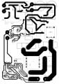
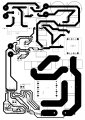
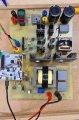
Also attached a picture of my circuit
 

Attachments

Ian0

Joined Aug 7, 2020
10,293
It is coupled from the drain through the gate-drain capacitance. Lower values of Rg are better.
Perhaps it needs a snubber across the MOSFET.
How about posting your circuit diagram?
 

Thread Starter

PowerSayan

Joined Oct 21, 2023
9
It is coupled from the drain through the gate-drain capacitance. Lower values of Rg are better.
Perhaps it needs a snubber across the MOSFET.
How about posting your circuit diagram?
I'll try to play around with Rg again when I get to the labs and see the results. I had a snubber and it did help a bit, but still couldn't get past 500mA I think. Ended up blowing two of the switches. And are you saying its then not neccesary to add the wire from the negative to the source, with the gate-source capacitance.
 

Ian0

Joined Aug 7, 2020
10,293
Have you checked the obvious things like the transformer phase (input and output should be IN phase) and does the transformer have a gap? (It should have either no gap or a very small gap)
There should always be a horizontal line halfway up on the drain waveform as on F009TEK. It doesn't have to be very long, but if it disappears and the rising waveform goes up all in one go, then your mark:space ratio is too high.
 

Thread Starter

PowerSayan

Joined Oct 21, 2023
9
Have you checked the obvious things like the transformer phase (input and output should be IN phase) and does the transformer have a gap? (It should have either no gap or a very small gap)
There should always be a horizontal line halfway up on the drain waveform as on F009TEK. It doesn't have to be very long, but if it disappears and the rising waveform goes up all in one go, then your mark:space ratio is too high.
So the transformer doesn't have a gap in it. Previously my transformer was actually the wrong orientation which gave a weird waveform across Vpri, but when I switched it back it gave the blue wavefom you see. I also have made sure to check that the duty cycle, (presume that is mark:space ratio), is 40% and limited it to a max of 45% for this converter.
 

Ian0

Joined Aug 7, 2020
10,293
So the transformer doesn't have a gap in it. Previously my transformer was actually the wrong orientation which gave a weird waveform across Vpri, but when I switched it back it gave the blue waveform you see. I also have made sure to check that the duty cycle, (presume that is mark:space ratio), is 40% and limited it to a max of 45% for this converter.
If the transformer has no gap, it has a large primary inductance. The risetime is controlled by a resonance between MOSFET capacitance and transformer inductance, and can sometime be quite slow, requiring the mark-space ratio to be reduced. A small gap can sometimes help by reducing that inductance and speeding up the rise time.

Is the gate waveform real? i.e. is your scope earth connected directly to the source, not to some 0V connection elsewhere in the circuit? If you have an old scope probe that is broken, take the cable and solder it to the points where you want to measure. Because the probe is no longer divide by 10, you will need a series resistor to prevent its capacitance upsetting the circuit. 47Ω should do for studying gate waveforms, because it is large enough in comparison to the output resistance of the gate driver.
 

Thread Starter

PowerSayan

Joined Oct 21, 2023
9
Do you think making a new transformer with lower leakage inductance could then perhaps solve the problem. It currently has 7uH of leakage on the primary side and around 1220uH inductance.

Then for the gate waveform I measured, I have a probe point at the gate of the mosfet that I soldered in and then another one at the source a bit further away. Could these probe points perhaps be causing a problem?
 
Top