Two stage BJT amplifier with feedback

Thread Starter

The Electrician

Joined Oct 9, 2007
2,971
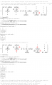
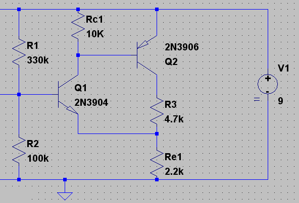
I did my spice analysis using the built-in model for the 2N3904 transistor.

I decided to determine the actual β for each transistor at its operating point. I inserted a 1 milliohm resistor in series with each base and collector. I then applied a small (.05 mV) 1 kHz signal at the input, and had spice calculate the ratio Ic/Ib for each transistor. You have to be sure to only calculate the ratio for the AC component of the signals.

I also adjusted the value of RFB until the signal at the emitter of Q1 was essentially zero. For my spice analysis, this happened when RFB was 2240 ohms.

Spice takes into account things that our simple model in this thread doesn't take into account.
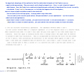
 

Jony130

Joined Feb 17, 2009
5,487
Since I am the European so I use BC549 model.
And I change the ac-gain to 304; and 203. In pspice (Orcade) its quite easily to check and change the Hfe. Or any parameter of a model.
NAME Q_T4 Q_T5
MODEL BC549A-X1 BC549C-X
IB 1.10E-05 3.17E-06
IC 2.03E-03 9.52E-04
VBE 6.75E-01 6.57E-01
VBC -3.29E+00 -3.09E+00
VCE 3.97E+00 3.74E+00
BETADC 1.86E+02 3.01E+02
GM 7.59E-02 3.65E-02
RPI 2.67E+03 8.32E+03
RX 2.06E+00 0.00E+00
RO 5.95E+04 2.85E+04
CBE 5.13E-11 5.70E-11
CBC 2.30E-12 2.99E-12
CJS 0.00E+00 0.00E+00
BETAAC 2.03E+02 3.04E+02
CBX 0.00E+00 0.00E+00
FT 2.25E+08 9.68E+0
And I get minimum for RFB=2.278K
 

Thread Starter

The Electrician

Joined Oct 9, 2007
2,971
I promised to show how the admittance matrix method as promulgated by Jacob Shekel is used to solve the circuits of this thread.

This post has 2 attachments that show how an admittance matrix is constructed by inspection from the circuit topology.

Also, see:

http://web.ecs.baylor.edu/faculty/grady/EE411_Fall2011_Week_02.pdf

Especially see the section titled "Building the admittance matrix".
 

Attachments

Last edited:

Thread Starter

The Electrician

Joined Oct 9, 2007
2,971
Here are 2 more attachments showing the building of the admittance matrix for the subject circuits.

I should mention that the transistor Y matrices assume that hre is zero and hro (ro) is infinite.
 

Attachments

Last edited:

Thread Starter

The Electrician

Joined Oct 9, 2007
2,971
Here are the final 2 attachments showing the Shekel's method in action.

As I mentioned earlier in the thread, if anybody is interested in a copy of Shekel's paper, post a disguised, valid, email address and I'll send you a copy.

I may expand the matrix shown in these attachments to include the capacitors and see if the cause of the low frequency oscillations Jony130 and I see with a spice simulation can be explained.
 

Attachments

steveb

Joined Jul 3, 2008
2,436
... attachments showing the building of the admittance matrix for the subject circuits.
This is a nice method. I was wondering if you could offer your opinion about how successful this technique is in providing design insight when analyzing a circuit. Since you have used this method to some extent, your feedback would be helpful because it's diffucult to form an objective opinion without sufficient experience.

I ask because, through the years, I've looked at various different approaches. Some are very neat and give answers efficiently, but without providing much design insight. Other methods are cumbersome, but the extra work provides the reward of good physical insight. I've always felt that a method that provides insight is much preferred for doing original design work.

In any serious design work, I always end up going back to my old training with signal flowgraphs and Mason's gain formula because of the insight it provides me. Development of the flowgraphs and the application of Mason's formula clearly identify the transmission and feedback paths. It then becomes possilble to improve the design at the flowgraphs/transmission/feedback level by adding or canceling out transmission or feedback paths, and then see if that is easily accomplished with a circuit change. It takes work to figure out the flowgraph that provides the best insight, and Mason's gain formula is really a pain (and prone to errors) when the number of nontouching loops gets large. But, the computer based symbolic processors can easily double check the final formulas by directly entering all flowgraph equations and using the linear solver.

Anyway, it seems to me that the admittance matrix has potential to provide insight. If one can see how changing some matrix elements will accomplish a design goal, then it's seems possible to identify how to implement that matrix change in circuitry. What isn't clear to me (due to lack of experience with this method) is whether it is easy to identify how the change of matrix elements impacts the design performance. Please share your thoughts about this aspect of the method. Personally, I am curious, and I think it is good information for others to have. Irrespective of how the method performs in this respect, this strikes me as an efficient and powerful approach. Also, there is no rule that says that design requires the use of only one method. If two methods each have distinct advantages to provide different types of intuitive insightful, then both should be used.
 

Thread Starter

The Electrician

Joined Oct 9, 2007
2,971
You raise an important and difficult consideration.

If you end up with a symbolic expression for some aspect of a circuit's performance, it must be the same no matter what method you used to get it. If a circuit has very many nodes, then a symbolic solution gets rapidly out of hand, and while it may be correct, it probably offers no insight. This problem is exacerbated by the fact that the symbolic algebra programs usually don't simplify a complicated expression the way a human would, isolating important circuit elements in an easy-to-understand subexpression perhaps. As you say, the signal flow graph method can help with that.

For example, often a human would show that two resistors appear effectively in parallel by writing part of an expression as ...R1||R2..., but no computer algebra program I've used does that. You always end up with a mess of algebra, and sometimes it may be possible to whip it into some form that may be helpful, but as I say, if there are very many nodes, and you include them all, it remains a mess!

I mentioned in another thread that Professor Middlebrook (http://ardem.com/whatis_D_OA.asp) notes that analysis of relatively simple circuits can generate complicated expressions which he calls "high-entropy" expressions. He shows methods to generate expressions that can give insight. His work is the best I've seen concerning this problem.

Also see: http://www.aus.edu/engr/ele/documents/AnalogCircuitAnalysisUsingaReuseMethodology.pdf

Using your engineering experience to make approximations, or to eliminate elements you know don't affect things much, is one key thing to do.

There's no really satisfactory answer, but what I have done when faced with a really complicated circuit is to use my engineering experience to select a few elements that I know are important and set up and solve the system with only those elements left in symbolic form, the rest left in numeric form. Then you can often see what the important elements are doing.

The main advantage of Shekel's method is that the individual elements of the Y matrix are simple and it only gets complicated when you invert the matrix. With such simple elements, the probability of getting them right is high, and the error prone massive amount of algebra needed to derive final expressions is done by the computer, without error.
 

Thread Starter

The Electrician

Joined Oct 9, 2007
2,971
Here's a fourth image showing how to derive formulas for the most complicated circuit, which really isn't very complicated. We can see how formulas rapidly get out of hand for a circuit with only a few components.

Rather than have formulas for each circuit, it's better to just know how to analyze them, with Shekel's method for example, or any other method that will do the job.

If you solve the circuit symbolically rather than numerically, you will end up with a "formula" for that circuit.

But with the computing power available nowadays, why bother with formulas? Just remember a method of solution and apply it.
 

Attachments

Last edited:

Jony130

Joined Feb 17, 2009
5,487
Can you tell witch maths software that you using

P.S can you derive formulas for this circuit using Shekel's method.
 
Last edited:

Thread Starter

The Electrician

Joined Oct 9, 2007
2,971
In post #48, the third image showed how to derive the voltage gain formula for a common emitter stage with an external emitter resistor.

Just to show what kind of computing power is available for cheap, I solved the same problem with symbolic algebra on a pocket calculator, an HP49G+ (the HP50G is currently available and has identical capability).

Attached are two images. The first shows the circuit Y matrix. The symbol RE is a reserved word on the calculator, so I had to use rE for the external emitter resistor.

The calculator is able to invert the Y matrix and calculate the voltage gain, Z(2,1)/Z(1,1), symbolically. The result is shown in the second image.

The calculator can operate on symbolic matrices up to 4th order in a reasonable time, but a 5th order symbolic matrix takes a couple of hours to invert.

But 2nd, 3rd and 4th order matrices suffice to solve most simple one transistor circuits. The calculator can invert matrices with complex elements, so circuits with reactive elements can be solved, symbolically or numerically.

And, if you solve numerically rather than symbolically, then 10th order presents no problem. In fact, I derived the numeric solutions I posted in this thread using the calculator.
 

Attachments

Thread Starter

The Electrician

Joined Oct 9, 2007
2,971
Can you tell witch maths software that you using

P.S can you derive formulas for this circuit using Shekel's method.
I'm using Mathematica, but I think you could probably use any of the other programs capable of symbolic linear algebra, such as Maple or the free one, Maxima.

I solved your circuit with the nodes numbered like this:

Node 1 = base of Q1
Node 2 = emitter of Q1
Node 3 = collector of Q1
Node 4 = collector of Q2

The result shows the voltage gain from node 1 to all of the other nodes, and the driving point impedances of all the nodes with the assumption that the input node is open circuited.

To determine the impedances as they would be with the input driven from a voltage source, the first row and column of the Y matrix should be deleted and then the reduced Y matrix should be inverted.

I arbitrarily set beta1 and beta2 = 200, and I set re1=40 ohms and re2 =25 ohms.

Then I evaluated the gains and impedances and I got:

gains:
1
.99986
-.01133
3.1199

Impedances:
76644
3.156
29.82
45.068
 

Attachments

Last edited:

Thread Starter

The Electrician

Joined Oct 9, 2007
2,971
Ku=1+(R3/Re1)=3.1363V/V
Can you show how this method work whit the opamp circuit?
Yes, I'll find a suitable opamp circuit to demonstrate the method.

I've attached another image showing the how the gain expression for your circuit becomes simplified as I allow the transistor parameters that control gain to approach limiting values giving increasing gain.

Notice the final value.

To steveb: this could be a technique to help with the insight problem mentioned earlier.
 

Attachments

steveb

Joined Jul 3, 2008
2,436
To steveb: this could be a technique to help with the insight problem mentioned earlier.
Yes, that's a good idea.

Just to expand on this, on this boring saturday; :) - I'm not tying to take the thread off topic, but some general design comments seem relevant with the discussion of this admittance matrix analysis approach, or any approach, for that matter.

There is one thing which (perhaps?) has not been explicitly mentioned. It's something that you know very well and relates to this technique you just used, but it's worth stressing for the benefit others. The form of the equations that you generate is very conducive for simplifications. Your expressions are usually written as a ratio of numerator over denominator. Both the numerator and denominator are always a sum of a finite number of terms. This standard form allows one to plug in typical values and then identify terms that are less significant. Very often, a "high entropy" equation, becomes "low entropy" equation when the components are tuned properly. This can happen if the components are tuned so that a term is negligible, or two terms of opposite sign nearly cancel.

The cancellation of opposite terms in the numerator is generally induced by negative forward transmission terms, while cancellations in the denominator are generally induced by positive feedback. Positive feedback always brings up the issue of stability and any cancellation has inherent sensitivity concerns. This is why stability and sensitivity analysis are critical in any good design process. It is very easy (and dangerous) to use the "low entropy" equations for design and then forget that they are not a perfect representation of the system.

The tuning of values to create negligible terms is useful to minimize sensitivity issues. Any term that has sensitivity to temperature, aging, noise or component uncertainty can be controlled by making sure that it is one of the smaller terms in the numerator or denominator. Often negative feedback is used to aid in this.

I think there are two separate issues with regards to the insight problem. The first is how to get a "low entropy" equation for the stated topology, and the second is how to modify the topology to provide design flexibility. The first issue is usually easier to handle by the technique of neglecting or canceling terms. The component values are basically chosen to create the "low entropy" relations important for a good robust design.

If component tuning does not produce the required effects, then the design must be modified. Then, the designer must figure out what new components to add to get the desired result. This is where the analysis technique, and the designer's creativity, are really put to the test. Somehow the designer has to put together a toolset that works for him. Sometimes intuition can magically reveal the design structure that will provide the needed flexibility. In such cases the analysis technique is less critical. Just crunch out the formulas and do the component tuning, formula reduction, stability analysis and sensitivity analysis. Other times, "the muse does not show her face", and we need analysis techniques to provides a view of the internal structures to allow good ideas to be developed more systematically. I am not aware of any approach that eliminates the need for good intuition and creative thinking, but perhaps the admittance matrix approach becomes one method to provide deeper insight. Personally, I plan to try it along side other methods in any future work, and then see if it should become another tool in the box.

This is all well-known to the experienced designers, but maybe is useful information for those beginning the process. I think the fun thing about analog circuit/system design is that it is still one of those areas of electrical engineering that has not fully yielded to a systematic "turn-the-crank" approach. You could argue that we now have it easier than past engineers for design at low frequency, but really we now have higher performance specs due to our better technology, and go into the megaHertz and intuition and individuality still play a big role in my opinion. The location of the frontier may have moved a little, but it's still a rough-and-tumble landscape out past the gates.
 
Last edited:

Thread Starter

The Electrician

Joined Oct 9, 2007
2,971
Can you show how this method work whit the opamp circuit?
Here's an example of an opamp circuit solved with the Y matrix method.

The first attachment shows the circuits solved.

There is an even more comprehensive method called Modified Nodal Analysis that can be used and which deals with opamps in a better way, and even transformers. I'll see if I can put together an example of its use.
 

Attachments

Thread Starter

The Electrician

Joined Oct 9, 2007
2,971
Back in post #18, I said:

"Now, to extend the problem, imagine this. Build each circuit, my original one and the one you analyzed and enclose each one in a black box. Each circuit's reference node (ground) is connected to the metal of the box. The other 5 nodes are connected to terminals on the outside of the box. Since both circuits have exactly the same gains from node 1 to the other nodes, how can we tell them apart?"

I guess everyone gave up on that one, so here is an attachment with the solution I had in mind.

See how easy it is once you have the admittance matrix for the circuit.
 

Attachments

Last edited:

Thread Starter

The Electrician

Joined Oct 9, 2007
2,971
At this web site:

http://people.seas.harvard.edu/~jones/es154/lectures/lecture_3/bjt_amps/bjt_amps.html

you'll find an analysis of the common emitter stage with external emitter resistor. His analysis is tedious, but he gets it right except in the final expression for Av where he has in the first set of curly braces {1-(β+1)...}.

The (β+1) term shouldn't be there.

I sent him an analysis using Shekel's method which is attached. You can see the advantage of using a systematic method.
 

Attachments

anhnha

Joined Apr 19, 2012
905
Here's an example of an opamp circuit solved with the Y matrix method.

The first attachment shows the circuits solved.

There is an even more comprehensive method called Modified Nodal Analysis that can be used and which deals with opamps in a better way, and even transformers. I'll see if I can put together an example of its use.
@The Electrician : I realized that you don't need to rewrite admittance for nodes 1, 3, 5 because what you rewrote added no new info to the admittance matrix.
 
Top