Two Stage Audio Amp

Thread Starter

aac044210

Joined Nov 19, 2019
178
If R1 = 3.3K as in the original circuit there is no clipping. I still don't know why the biasing resistor is 120K. One
would have accounted for the 293mV when computing the value for the resistor. It doesn't matter what value
of bias resistor you use in LTS, the base bias ends up at 700mV and the current is about 3.3 μA.
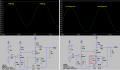
I just breadboarded the circuit and it doesn't work at all in the real world.
 

Thread Starter

aac044210

Joined Nov 19, 2019
178
The 120k biasing resistor is also used for DC negative feedback and adds a little AC negative feedback.
Connect an added 3.9k resistor parallel with RE2 and the clipping is eliminated and the maximum output level can be higher.
There is no clipping in my simulation. You have the wrong feedback resistance and you
have clipping. I keep asking why the bias resistance is 120K? In the simulation it doesn't matter what
bias resistor is used, the bias voltage is always 700mV with a current of 3.3 μA. When breadboarded, the circuit
does not work at all. The bias voltage is too low at 650mv to turn Q1 on.
 

Audioguru again

Joined Oct 21, 2019
6,826
I am sorry I had the wrong value feedback resistor. I corrected it and got clipping. Then I turned up the input level from 15mV peak to 17mV peak so you can clearly see severe clipping.

Then I added a resistor parallel with RE2 so that the clipping was symmetrical at higher levels. The new resistor is 3.3k.
RE is 1k and when paralleled with 3.3k makes 767 ohms which is not a standard value. I tried the circuit with 750 ohms for RE but then the bottom of the waveform began to clip at this high input level.
 

Attachments

Audioguru again

Joined Oct 21, 2019
6,826
Try my added 3.3k resistor. When RB is 120k then there is no clipping. Changing RB to 82k causes the top of the waveform to clip. changing RB to 150k causes the bottom of the waveform to clip.
 

Ylli

Joined Nov 13, 2015
1,092
The bias for the first stage comes from the emitter of the second stage. The current through that 120K resistor is very small, and variations in its resistance will only be seen as slight variations in the emitter voltage, and therefore the current, in the second stage.

I tweaked some values to increase the power handling capability and to center it up a bit better.
 

Attachments

Your DVM adds a resisance, maybe 10 ohms, maybe less maybe more. You need two of them or insert a small value resistor in C and E and measure the voltage across it. The reactance of C will vary with frequency.

You can also build a zero resistance ammeter or I-V converter which will drop <1mV. I've built them to a bipolar +-100 mA (4 ranges.+-10V output full scale) and 2 and 4 terminal switchable.
 

Thread Starter

aac044210

Joined Nov 19, 2019
178
The bias for the first stage comes from the emitter of the second stage. The current through that 120K resistor is very small, and variations in its resistance will only be seen as slight variations in the emitter voltage, and therefore the current, in the second stage.

I tweaked some values to increase the power handling capability and to center it up a bit better.
Thanks for the reply but this file cannot be opened with LTSpice.
 

Audioguru again

Joined Oct 21, 2019
6,826
You want a fairly high input impedance so the value of the 120k resistor must he high but not high enough to disturb the normal voltages. The base current of Q1 is about 3uA so the voltage across the 120k resistor is only 3u x 120k= 0.36V which is fine.

If you reduce the 120k value a little then Q1 conducts more and Q2 conducts less so the top of the output waveform will be clipping. If you increase the 120k value then Q1 conducts less and Q2 conducts more so the bottom of the output waveform will be clipping.
 

Thread Starter

aac044210

Joined Nov 19, 2019
178
You want a fairly high input impedance so the value of the 120k resistor must he high but not high enough to disturb the normal voltages. The base current of Q1 is about 3uA so the voltage across the 120k resistor is only 3u x 120k= 0.36V which is fine.

If you reduce the 120k value a little then Q1 conducts more and Q2 conducts less so the top of the output waveform will be clipping. If you increase the 120k value then Q1 conducts less and Q2 conducts more so the bottom of the output waveform will be clipping.
Thanks Audioguru that makes good sense. My next step is to come up with some rules of thumb for designing this circuit
from scratch.
 
Top