Two Stage Audio Amp

Thread Starter

aac044210

Joined Nov 19, 2019
178
Hello:

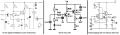
I am a hobbyist. I built this 2 stage amp and it seems to work fine. I measured the dc current for the transistors
and found the results to be confusing. I have taken these measurements multiple times and can't see how IE2
could be less than IC2. I would appreciate some help.

1574181606171.png

IC1 1.02 mA
IB1 6.2 uA
IE1 1.03 mA

IC2 1.11 mA
IB2 6.2 uA
IE2 1.06

Thanks
 

Thread Starter

aac044210

Joined Nov 19, 2019
178
Don't think it can be, you must be measuring it wrong. Or measuring it in the wrong place.
No, I am measuring in the right places and in the same way that I measured the stage 1 transistor
currents. I have checked the connections and they appear about as secure as you can get with
a protoboard build. I have also tried multiple transistors with the same result. Is it possible that
these transistors are flakey?

It appears that the βdc for these 2N3904s is only 161.
 

Audioguru again

Joined Oct 21, 2019
6,826
A current meter has a resistance and its leads pickup interference that upsets the circuit you are measuring.
The datasheet for a 2N3904 says that at an Ic of 1mA, its minimum beta (hFE) is only 70, typical shown on a graph is 230.

Why are the values of the base voltage divider resistors so low and why are the values of the 220uF and 100uF coupling capacitors so high?
 

Thread Starter

aac044210

Joined Nov 19, 2019
178
A current meter has a resistance and its leads pickup interference that upsets the circuit you are measuring.
The datasheet for a 2N3904 says that at an Ic of 1mA, its minimum beta (hFE) is only 70, typical shown on a graph is 230.

Why are the values of the base voltage divider resistors so low and why are the values of the 220uF and 100uF coupling capacitors so high?
Hi Audioguru. Thanks for the info. I checked the values using C= 1 / 2πf1R*0.1 and they came out to 130μF and 80μF. Is that
formula incorrect? What would you suggest for the capacitor values?
 

Audioguru again

Joined Oct 21, 2019
6,826
The biasing resistors and the input impedance of the transistors are parts that need to be calculated for coupling capacitors. The negative feedback added to the input transistor also lowers its input impedance.

It seems that the original AC-coupled preamp has a negative output swing of 2V peak but its positive output swing is squashed at only 1.6V peak which is even-harmonics distortion. The distortion will be much worse at higher output levels.
Also, even though the original circuit used HUGE coupling capacitors, its deep low frequencies are cut.

For years, audio opamps have been used for preamps that have extremely low distortion. Here are three old circuits with transistors that were used many years ago:
 

Attachments

AnalogKid

Joined Aug 1, 2013
12,128
I have taken these measurements multiple times and can't see how IE2 could be less than IC2.
You don't say how you are measuring the currents. ***Assuming*** that it is by inserting a DMM in series with the emitter and collector resistors, then it makes perfect sense.

When you insert a small resistance in series with the 1K emitter resistor, the total emitter resistance increases. The base and emitter voltages are held constant by the base bias resistors, so the emitter current is decreased slightly per Ohm's Law. When you insert a small resistance in series with the collector resistor, the collector current does not change because it is not dependent on the collector resistance, only on the base voltage and current, and the emitter resistance.

To see this exaggerated for effect, first increase the emitter resistor to 1100 ohms and recalculate the circuit voltages and currents. Then return the emitter resistor to 1 K, increase the collector resistor to 4K, and recalculate.

AND - add reference designators to all components. This would have been a much shorter response if I could have said R2, R4, etc.

ak
 

Thread Starter

aac044210

Joined Nov 19, 2019
178
The biasing resistors and the input impedance of the transistors are parts that need to be calculated for coupling capacitors. The negative feedback added to the input transistor also lowers its input impedance.

It seems that the original AC-coupled preamp has a negative output swing of 2V peak but its positive output swing is squashed at only 1.6V peak which is even-harmonics distortion. The distortion will be much worse at higher output levels.
Also, even though the original circuit used HUGE coupling capacitors, its deep low frequencies are cut.

For years, audio opamps have been used for preamps that have extremely low distortion. Here are three old circuits with transistors that were used many years ago:
Thanks Audioguru
 

Thread Starter

aac044210

Joined Nov 19, 2019
178
You don't say how you are measuring the currents. ***Assuming*** that it is by inserting a DMM in series with the emitter and collector resistors, then it makes perfect sense.

When you insert a small resistance in series with the 1K emitter resistor, the total emitter resistance increases. The base and emitter voltages are held constant by the base bias resistors, so the emitter current is decreased slightly per Ohm's Law. When you insert a small resistance in series with the collector resistor, the collector current does not change because it is not dependent on the collector resistance, only on the base voltage and current, and the emitter resistance.

To see this exaggerated for effect, first increase the emitter resistor to 1100 ohms and recalculate the circuit voltages and currents. Then return the emitter resistor to 1 K, increase the collector resistor to 4K, and recalculate.

AND - add reference designators to all components. This would have been a much shorter response if I could have said R2, R4, etc.

ak
Yes I used a dmm. Thanks AnalogKid
 

Thread Starter

aac044210

Joined Nov 19, 2019
178
Yes I used a dmm. Thanks AnalogKid
Hi

Hi Bordodynov:

That circuit is slick. Works great. Can you tell me how you came up with a bias resistor of 120K. I haven't
worked with this configuration before.
I disconnected the 120K resistor from the base and foun that there is 293mV between the base and ground. If you want to have a toyal of 700m\v on the base then the 120K resistor must develop another 400mV. The thing is, how would you know that there is already 293mV on the base? I assume that you computed the base current to be IB = IC / β = 1mA / 300 = 3.3 μA. Thanks
 

Audioguru again

Joined Oct 21, 2019
6,826
I disconnected the 120K resistor from the base and found that there is 293mV between the base and ground. If you want to have a total of 700m\v on the base then the 120K resistor must develop another 400mV. The thing is, how would you know that there is already 293mV on the base?
The 120k resistor R13 feeds its voltage and current to the base of the transistor. With R13 disconnected from the base then how can the base have the 293mV that you measure?? Base-emitter reverse-bias leakage current?? But the base-emitter is never reverse-biased when R13 is connected.
 

Bordodynov

Joined May 20, 2015
3,431
I advise you to use Ohm's law to determine the currents. Measure the voltage on the resistor and then calculate the current. You do not need to cut into the circuit with an ammeter.
 

Thread Starter

aac044210

Joined Nov 19, 2019
178
I advise you to use Ohm's law to determine the currents. Measure the voltage on the resistor and then calculate the current. You do not need to cut into the circuit with an ammeter.
I ran this circuit with LTSpice and found the 293mV on Q1 base when it is open. How did you
find the value of the bias resistor to be 120K? Spice file is attached. Thanks.
 

Attachments

Audioguru again

Joined Oct 21, 2019
6,826
I simulated your attachment and found that with the 120k resistor connected then the output has asymmetrical clipping because it is not biased correctly. With the 120k resistor disconnected then the base of the first transistor measures the 293mV which is caused by transistor leakage current.
 

Attachments

Thread Starter

aac044210

Joined Nov 19, 2019
178
I simulated your attachment and found that with the 120k resistor connected then the output has asymmetrical clipping because it is not biased correctly. With the 120k resistor disconnected then the base of the first transistor measures the 293mV which is caused by transistor leakage current.
If R1 = 3.3K as in the original circuit there is no clipping. I still don't know why the biasing resistor is 120K. One
would have accounted for the 293mV when computing the value for the resistor. It doesn't matter what value
of bias resistor you use in LTS, the base bias ends up at 700mV and the current is about 3.3 μA.
 
Last edited:

Audioguru again

Joined Oct 21, 2019
6,826
The 120k biasing resistor is also used for DC negative feedback and adds a little AC negative feedback.
Connect an added 3.9k resistor parallel with RE2 and the clipping is eliminated and the maximum output level can be higher.
 
Top