 Facebook
 Google
 GitHub
 Linkedin
Hi all!,
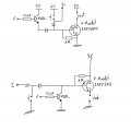
I have these 2 circuits, the one with the P-Mosfet works properly, the other with N-Mosfet doesn't work.
I use to On/Off a circuit pushing a button. Pressing the button the Mosfet starts drive and supply a microcontroller. One IO from the micro is put to HIGH and connect to "1" so the mosfet continue driving. If you press the button for a while, the signal goes to another IO to the micro and the software out a LOW to "1" disconnecting the circuit.
What I'm doing wrong?
Attachments
-
 66.5 KB Views: 26


