Facebook
 Google
 GitHub
 Linkedin
Hi everyone. I am a bit of a hobbyist but haven't done any electronics work in a while and am new to this forum. I am currently working on a project for fun. The basic idea of what I want the circuit to do is this:
Main Function of Circuit:
----------------------------
1) User switches power on to circuit.
2) Piezo siren triggers every few seconds for .5 seconds or so
3) User adjusts potentiometer to set a time limit from 30 to 60 seconds.
4) User presses a button which starts the first 555 timer as a monostable oscillator and stops the piezo siren from going off.
5) After the first 555 timer sequence is complete, the second 555 timer is triggered as an astable oscillator to start, this powers a piezo siren every couple of seconds for a .5 second interval or so.
6) User turns off power to circuit and siren doesn't play anymore.
Other Functions:
---------------------
1) User can switch an LED off and on while the power is on to the circuit.
I had all 6 steps working perfectly on a breadboard and moved on to soldering everything onto a PCB board, but that is where my troubles started.
The Process I have gone through so far:
--------------------------------------------
After soldering everything onto the board (including the CR2032 battery holder), the LED and the rest of the circuit did not turn on, so I removed the batteries. I used a very small flathead screwdriver to make sure the areas between different solders were clear of any possible trace lines and tried powering on again for a short time, but no luck. Since then, I used a dremel tool to REALLY make sure none of my solder connections were touching, then cleaned the bottom of the board with rubbing alcohol and a toothbrush. After letting it dry for a while, I tried a final time but to no avail.
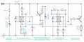
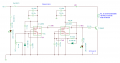
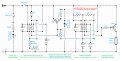
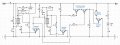
I have re-drawn the schematic (painstakingly) from the actual finished soldered circuit and checked it against the original I drew up that worked in the breadboard, but haven't been able to find any differences. At this point, I am thinking that I may have blown something due to a short resulting from a bad solder touching something it shouldn't have. With all of the components soldered in, taking them all out and replacing them with new ones would take forever, and if that isn't the problem then I'm still stuck and now just out more $. Nothing looks visibly damaged but I am not sure if any of them would show visible signs if they were burned out. The other alternative is that my original circuit was bad and perhaps I overloaded the transistors or 555s.
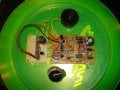
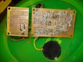
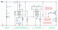
I have attached the schematic I re-drew from the actual soldered board as is, along with pictures of the actual circuit. The siren came with a built in driver circuit which I have removed from its original enclosure and placed on a separate breadboard from the main board. All transistors are NPN. At this point, I am 99% certain that the circuit is exactly as shown in my schematic that I am attached and does not have anymore soldering issues, which leaves either fried components or a bad original circuit to blame. Right now, when I do a check of resistance from power to ground with both of my switches open and without the battery attached, I get a resistance of .3 to .5 Ohms which doesn't seem right at all, but my electronics knowledge is too inferior to really interpret what would cause this. My gut tells me some kind of short is to blame, but I have triple checked all the wires and solders and can't find anything. If I blew a 555 or transistor, would this cause a short internally, or would the component just not work?
Conclusion:
----------------------
I am okay with replacing components but would prefer not to replace everything if possible, and would like to know if the schematic is correct first before I risk blowing anything else. Sorry for the length of the post, but I wanted to make sure I provided as much information as possible about the situation so that anyone wishing to lend me a hand would be well informed. I hope I at least organized it somewhat coherently. Below this you will find links to my main components.
Thank you for any help that can be provided as I have spent way more time on this than I should have already! Also, thank you for your patience in looking at my diagram as I did not use standard symbols for my capacitors and potentiometers but I labeled them.
Components:
-----------------------------
LM555 Timers:
http://www.radioshack.com/product/index.jsp?productId=2062596
NPN Transistors:
http://www.radioshack.com/product/index.jsp?productId=2062586
Piezo Siren with built in driver circuit:
http://www.radioshack.com/product/index.jsp?productId=2062405
CR2032 3V/225mAh Lithium Coin Cells (I use 2 for a total of 6V or so):
http://www.radioshack.com/product/index.jsp?productId=3802113
Resources I used:
------------------------------
This prevents the first 555 from starting when power is turned on:
http://home.cogeco.ca/~rpaisley4/LM555.html#10
(LM555 Power-Up Reset Method 2)
Here's where I got information on how to use NPN transistors as NOT gates, as AND gates, and as a switch:
http://www.kpsec.freeuk.com/trancirc.htm
.
Main Function of Circuit:
----------------------------
1) User switches power on to circuit.
2) Piezo siren triggers every few seconds for .5 seconds or so
3) User adjusts potentiometer to set a time limit from 30 to 60 seconds.
4) User presses a button which starts the first 555 timer as a monostable oscillator and stops the piezo siren from going off.
5) After the first 555 timer sequence is complete, the second 555 timer is triggered as an astable oscillator to start, this powers a piezo siren every couple of seconds for a .5 second interval or so.
6) User turns off power to circuit and siren doesn't play anymore.
Other Functions:
---------------------
1) User can switch an LED off and on while the power is on to the circuit.
I had all 6 steps working perfectly on a breadboard and moved on to soldering everything onto a PCB board, but that is where my troubles started.
The Process I have gone through so far:
--------------------------------------------
After soldering everything onto the board (including the CR2032 battery holder), the LED and the rest of the circuit did not turn on, so I removed the batteries. I used a very small flathead screwdriver to make sure the areas between different solders were clear of any possible trace lines and tried powering on again for a short time, but no luck. Since then, I used a dremel tool to REALLY make sure none of my solder connections were touching, then cleaned the bottom of the board with rubbing alcohol and a toothbrush. After letting it dry for a while, I tried a final time but to no avail.
I have re-drawn the schematic (painstakingly) from the actual finished soldered circuit and checked it against the original I drew up that worked in the breadboard, but haven't been able to find any differences. At this point, I am thinking that I may have blown something due to a short resulting from a bad solder touching something it shouldn't have. With all of the components soldered in, taking them all out and replacing them with new ones would take forever, and if that isn't the problem then I'm still stuck and now just out more $. Nothing looks visibly damaged but I am not sure if any of them would show visible signs if they were burned out. The other alternative is that my original circuit was bad and perhaps I overloaded the transistors or 555s.
I have attached the schematic I re-drew from the actual soldered board as is, along with pictures of the actual circuit. The siren came with a built in driver circuit which I have removed from its original enclosure and placed on a separate breadboard from the main board. All transistors are NPN. At this point, I am 99% certain that the circuit is exactly as shown in my schematic that I am attached and does not have anymore soldering issues, which leaves either fried components or a bad original circuit to blame. Right now, when I do a check of resistance from power to ground with both of my switches open and without the battery attached, I get a resistance of .3 to .5 Ohms which doesn't seem right at all, but my electronics knowledge is too inferior to really interpret what would cause this. My gut tells me some kind of short is to blame, but I have triple checked all the wires and solders and can't find anything. If I blew a 555 or transistor, would this cause a short internally, or would the component just not work?
Conclusion:
----------------------
I am okay with replacing components but would prefer not to replace everything if possible, and would like to know if the schematic is correct first before I risk blowing anything else. Sorry for the length of the post, but I wanted to make sure I provided as much information as possible about the situation so that anyone wishing to lend me a hand would be well informed. I hope I at least organized it somewhat coherently. Below this you will find links to my main components.
Thank you for any help that can be provided as I have spent way more time on this than I should have already! Also, thank you for your patience in looking at my diagram as I did not use standard symbols for my capacitors and potentiometers but I labeled them.
Components:
-----------------------------
LM555 Timers:
http://www.radioshack.com/product/index.jsp?productId=2062596
NPN Transistors:
http://www.radioshack.com/product/index.jsp?productId=2062586
Piezo Siren with built in driver circuit:
http://www.radioshack.com/product/index.jsp?productId=2062405
CR2032 3V/225mAh Lithium Coin Cells (I use 2 for a total of 6V or so):
http://www.radioshack.com/product/index.jsp?productId=3802113
Resources I used:
------------------------------
This prevents the first 555 from starting when power is turned on:
http://home.cogeco.ca/~rpaisley4/LM555.html#10
(LM555 Power-Up Reset Method 2)
Here's where I got information on how to use NPN transistors as NOT gates, as AND gates, and as a switch:
http://www.kpsec.freeuk.com/trancirc.htm
.
Attachments
-
 217 KB Views: 81
 -
 225.9 KB Views: 70
 -
 188.6 KB Views: 122
Last edited:


 . I'm actually down in Houston, so if either of you two ever make it down this way, look me up and I'll treat ya to a steak dinner for the help.