Tweaking solar garden light

Thread Starter

Frenchy

Joined Dec 6, 2020
15
I'm trying to refurb some "old" pathway solar lights. They were nice looking, relatively bright (when new), and I want to keep them
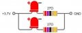
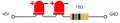
I've removed the original PCB and wired the 2 LEDs in series and power them under 6V with a 15 Ohm resistor (they were originally in parallel on the PCB, powered by a 900mAh Li-Ion battery)
I want to use a 2,200mAH 18650 battery per lamp (hoping the small solar panel will charge them), and was planning on using a TP4056 board + step-up converter to get 6V, or this type of board that does both:
https://www.amazon.com/Battery-Char...e4-aacb-629b44c08c72&pd_rd_i=B098989NRZ&psc=1
But I would like to use the solar panel to turn the light ON when it's dark and OFF under daylight.....How should I wire a MOSFET to do that, knowing only 40ma goes into the 2 LEDs?
Thanks
 

Attachments

MisterBill2

Joined Jan 23, 2018
27,164
Tohave the sola cells switch the lights OFF, you need a resistor to bias the gate to source junction ON, and then the solar cell output to push in ther opposite direction to switch the junction off. So you will need to examine the data sheets to know the voltages that switch off and on. Not difficult but not common.
 

Externet

Joined Nov 29, 2005
2,624
A 6V solar panel is enough to recharge a 18650 cell with no need for a booster board. Connecting white? LEDs in series is wrong as the turn-on voltage will be too high for the Li cell.
Suggest that you ´refurb' going back to the original circuitry, replacing/renewing whatever component is weak.
 

Thread Starter

Frenchy

Joined Dec 6, 2020
15
A 6V solar panel is enough to recharge a 18650 cell with no need for a booster board. Connecting white? LEDs in series is wrong as the turn-on voltage will be too high for the Li cell.
Suggest that you ´refurb' going back to the original circuitry, replacing/renewing whatever component is weak.
This is why I was thinking about a booster board, to get 6V from the 3.7V Li-Ion battery to power the 2 LED in series @ 40mA
 

Thread Starter

Frenchy

Joined Dec 6, 2020
15
Are you saying I should stick to this ?
I still need to know how to wire a MOSFET to turn ON and OFF the LEDs from the solar panel though......
 

Attachments

sghioto

Joined Dec 31, 2017
8,633
This might help if you are looking to build.
A 555 circuit configured through the setting of Rv1 to activate the LEDs as the voltage from the Solar Cell drops in the evening. Then deactivate later when the voltage rises above the setting of Rv2.
Rv1 and Rv2 allow independent adjustments for the ON and OFF settings.
1684544088655.png
 

Thread Starter

Frenchy

Joined Dec 6, 2020
15
This might help if you are looking to build.
A 555 circuit configured through the setting of Rv1 to activate the LEDs as the voltage from the Solar Cell drops in the evening. Then deactivate later when the voltage rises above the setting of Rv2.
Rv1 and Rv2 allow independent adjustments for the ON and OFF settings.
View attachment 294548
Cool, thanks........I did MANY years ago my own circuit printed boards with iron chloride, but I don't think I'm willing to do it again. Is there any prebuilt modules I can find (Amazon?) that would do that?
 

MrChips

Joined Oct 2, 2009
34,628
Cool, thanks........I did MANY years ago my own circuit printed boards with iron chloride, but I don't think I'm willing to do it again. Is there any prebuilt modules I can find (Amazon?) that would do that?
There are alternatives to etching your own boards.
There are many PCB manufacturers that will make your boards for an affordable price and short delivery times.

If you are planning on making many one-of-a-kind DIY prototype projects you can mill the PCB pattern on a small low cost CNC milling tool. Your turn around time is reduced to minutes. If you made design errors it easy to fix the error and remake the board.
 

Thread Starter

Frenchy

Joined Dec 6, 2020
15
This might help if you are looking to build.
A 555 circuit configured through the setting of Rv1 to activate the LEDs as the voltage from the Solar Cell drops in the evening. Then deactivate later when the voltage rises above the setting of Rv2.
Rv1 and Rv2 allow independent adjustments for the ON and OFF settings.
View attachment 294548
Will this circuit work exactly the same if I replace the 6V by 3.7V (1 x 18650 battery) and put the 2 LEDs in parallel with a 27 Ohm resistor each (as it is shown in post #6)?
 

Externet

Joined Nov 29, 2005
2,624
Will this circuit work exactly the same if I replace the 6V by 3.7V (1 x 18650 battery) and put the 2 LEDs in parallel with a 27 Ohm resistor each (as it is shown in post #6)?
Solar panels do not behave as you may think. They are current sources with their voltage collapsing depending on the load. It is not that they provide a voltage with their current changing under load
A 6V panel output that you measured (with no load?) may work perfectly well recharging a Li-ion cell with no overcharging if a drop trough diodes or else happens in the charging circuitry.
Yes your post #6 works for a Li cell, and post #1 does not work for white LEDs. And your 40mA figure may be wrong.
 
Last edited:

Thread Starter

Frenchy

Joined Dec 6, 2020
15
Solar panels do not behave as you may think. They are current sources with their voltage collapsing depending on the load. It is not that they provide a voltage with their current changing under load
A 6V panel output that you measured (with no load?) may work perfectly well recharging a Li-ion cell with no overcharging if a drop trough diodes or else happens in the charging circuitry.
Yes your post #6 works for a Li cell, and post #1 does not work for white LEDs. And your 40mA figure may be wrong.
Why #1 does not work for white LED at 6V? I did a test for 1 night to check how bright the lamp was, using a cheap step down converter (from my source available at the time aka a 18V Ryobi battery down to 6V) and it worked fine....About the current, I measured 80mA with the original PCB, where the 2 LEDs were wired in parallel...So I figured each LED will get 40mA
 

Externet

Joined Nov 29, 2005
2,624
A lithium cell does not provide 6V. Delivers from ~4.2V fully charged to ~2.5V discharged. Two white leds in series as #1 take at least 6V. Your Ryoby test at 6V is flawed to fake a Li cell supply.
If your currents measurement is done with overvoltage (6V instead of 3.7V,) your 40mA numbers will be too high and the LEDs can die prematurely.
 
Last edited:

wayneh

Joined Sep 9, 2010
18,087
The problem is that the panel is likely the limiting factor. In my experience you can add good, high-capacity batteries to one of these lights and they'll be great for a few days but then lose oomph. Most of mine are for Christmas decorations and that's the time of year with the absolute least sunlight per day, and plenty of cloudy days as well. So your situation could be different.

Two things are key, in my opinion, to make the most of the limited energy: 1) You don't want them coming on until it's fairly dark. My lights use a CdS photocell to detect light and that works very well until they get old. The CdS cell becomes less sensitive and the light turns on too early. Your's likely do not use the CdS cells (that tech disappeared a while ago) but however you tune the sensitivity to light, have them come on later in the evening. 2) These lights would work a lot better if they had a timer to shut them off after, say, 6 hours. You don't need them on from 2AM until daybreak and they're just wasting energy during those hours. I haven't seen any that shut off that way and perhaps that means there's a problem with that approach. Cost maybe? I don't know. I have some LED candles in the house that shut off on their own and they'll last months on a pair of AAs, so I don't think it's power consumption.
 

Thread Starter

Frenchy

Joined Dec 6, 2020
15
I probably haven't explained well:
-) The solar lamps look nice, and used to be bright when they were new
-) They were powered by a 3.7V 900mAh Li-ion battery (18500?), and 2 white LEDs (8mm) in parallel
-) There was a switch to select how long they would run once ON: 6h or 10h
-) But now, they are not so bright: all the batteries would have to be replaced, switches are rusted, some wires broken, etc....

My project:
-) Refurb the lamps (hammered paint, new posts with PVC tubes, etc....) - I did one, and it looks nice again
-) For the lights, I thought about several options:
1st option: Use the solar panel with 18650 batteries (2,200mAh) that I have laying around. Assuming the solar panel would be able to recharge the battery (I'm not so sure now), I was thinking to use a TP4056 charger module + booster to go from 3.7V to 6V and install the 2 LED in series with a 15 Ohm resistor to get 40mA OR TP4056 charger module, stay at 3.7V and install the 2 LEDs in parallel with 27 Ohm each - And in both case, I would need a circuit to turn them ON and OFF depending on the ambient light
By the way, isn't it possible that a 8mm white LED is designed to operate at 40mA without killing it quickly?

2nd option: Make it much more simple and replace the LEDs / electronic boards by 12V AC/DC led lamps and run a wire.....With 2nd option, I would have to find the best way to run the wires thru the post to the top of the lamp....

Keeping it solar will avoid to run wires from the house to each lamp, but will probably be more "complex"...
 
Top