tv-be-gone modification.

Thread Starter

burningbridges43

Joined Jan 6, 2009
15
Perhaps you've heard of it, a tiny remote that will turn off virtually any TV.
Good fun.

Anywho, Ive purchased a kit and wish to add a small timer that will trigger it to go off every 5 or 10 minutes.

Now seeing as how I am far from the electrical engineering wizard, I need some help figuring it out. would something like http://www.radioshack.com/product/index.jsp?productId=2062596 work? (combined with a resistor and capacitor right?) and where would I place such a piece?

Any help or guidance would be much appreciated.

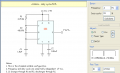
Here are the schematics for the kit:
 

SgtWookie

Joined Jul 17, 2007
22,230
So, you want to toggle every TV on/off within the proximity of the LEDs every 5 minutes?

Because that's what would happen.

The remote control power signal is a toggle; press once for on, then press again for off.
 

SgtWookie

Joined Jul 17, 2007
22,230
Funny that Radio Shack calls the LM555 a "precision timer" - it's anything but precise.

But I digress. ;)

Every 5 minutes, you'll want to apply GND briefly to pin 1 of the Attiny85v-10p.

The attached should do it.
 

Attachments

SgtWookie

Joined Jul 17, 2007
22,230
OK.

Build the kit first as per the instructions, and get it working. Then you'll have a success; something that you know works.

Then come back to this thread and we'll resume.
 

eblc1388

Joined Nov 28, 2008
1,542
If anyone is wondering what software is used for the 555 design shown in post#4 by SgtWookie, I have looked up the answer.

It is a software from Schematica called "555 Timer PRO/LITE" at this link.

555 Timer PRO and 555 Timer Lite (freeware)

While the PRO version costs a very reasonable amount the designer has so kind as to offer the LITE version as freeware. Sufficient to say the LITE version is a nice addition to your electronic tool library. If you like it, you might as well paid for the PRO version to support the designer.
 

SgtWookie

Joined Jul 17, 2007
22,230
Done. Now what?
Cool - it works?

If so, go back to the schematic I posted.

For R1, use a 4.7 Megohm resistor.
For R2, use a 47 Kilohm resistor.
For C1, use a 1.5 Microfarad capacitor.
You really don't need C2 for your application.

The output of the 555 goes to the output of your switch.
All of the grounds go to the ground of your already-built circuit.
All of the supply voltage inputs go to the supply voltage of your circuit.
You can use a CMOS 555, like the one that Radio Shack sells (TLC555N)
 
Last edited:

Thread Starter

burningbridges43

Joined Jan 6, 2009
15
Ug. I really hate being so naive.

The output of the 555 goes to the output of your switch.
All of the grounds go to the ground of your already-built circuit.
All of the supply voltage inputs go to the supply voltage of your circuit.
(TLC555N)
Im pretty sure I understand the first one-im attaching it right between the switch and the first capacitor correct?
I'm not sure I know where the grounds are on my circuit.
The supply voltage of my circuit=the black wire from the battery?

And I need a breadboard to construct this all on?

Thanks btw for all the help. Hope I'm not too much trouble.
 

SgtWookie

Joined Jul 17, 2007
22,230
Ug. I really hate being so naive.
We were all new to this kind of thing once, and young. ;)
Im pretty sure I understand the first one-im attaching it right between the switch and the first capacitor correct?
Pin 1 of the Attiny85.

I'm not sure I know where the grounds are on my circuit.
See S1? The left side of it is ground. Also, pin 4 of the Attiny85.

The supply voltage of my circuit=the black wire from the battery?
Pin 8 of the Attiny85 has the supply voltage on it.
Usually, the black wire from your battery will be the same as ground in the circuit, but use a meter to be certain.

And I need a breadboard to construct this all on?
Not really; you could construct it "dead bug" fashion. However, a breadboard would be a good place to test things on.

Thanks btw for all the help. Hope I'm not too much trouble.
You're welcome, and no - you're not too much trouble.

This site is about learning electronics. If you're actually learning, then this is the place to be. If you're not learning, then it's time to move elsewhere.
 

Thread Starter

burningbridges43

Joined Jan 6, 2009
15
Ok Im staring at the 555piece. How do I orient it to match your schematic?
And whats the doohickey (That's the technical term right?) coming out of three mean?
 

SgtWookie

Joined Jul 17, 2007
22,230
Ok Im staring at the 555piece. How do I orient it to match your schematic?
Well, it's just a schematic. In the drawing, the pins were placed in convenient locations to make the schematic easily readable.

The physical part is different.

Place it on the table in front of you, pins down, so that you can read the part number. There should be a notch on the top of the left end.

The pin on the left end on your side is pin 1. Count up towards the right (counterclockwise); 2, 3, 4.
Pin 5 is opposite pin 4 (the side away from you). From pin 5, count up (still going counterclockwise) to pin 8, which is opposite pin 1.

And whats the doohickey (That's the technical term right?) coming out of three mean?
That's a Tootsie pop, signalling for a right turn. :)

Seriously, that's just the symbol for a connector. You don't have to use a connector, you can wire it right to the switch.
 

Thread Starter

burningbridges43

Joined Jan 6, 2009
15
I have a notch (a circle actually) on the bottom left. I'm assuming the order of the pins is still the same though: starting with 1 on the bottom left (by the circle)

Resistors are symmetrical right? so it doesn't matter which way I put it in. I'm guessing this capacitor is not because one leg is longer than the other(marking it as positive). Which way does the capacitor go in?
 

SgtWookie

Joined Jul 17, 2007
22,230
I have a notch (a circle actually) on the bottom left. I'm assuming the order of the pins is still the same though: starting with 1 on the bottom left (by the circle)
Yes.

Resistors are symmetrical right? so it doesn't matter which way I put it in.
That's correct.
I'm guessing this capacitor is not because one leg is longer than the other(marking it as positive). Which way does the capacitor go in?
Usually, electrolytic capacitors have a marking of some type to indicate the negative lead; tantalum capacitors have a mark indicating the positive lead. Caps with radial leads (both coming from one end) usually have the negative lead slightly shorter.

The negative lead goes to ground.
 

Thread Starter

burningbridges43

Joined Jan 6, 2009
15
Back to these:
The output of the 555 goes to the output of your switch.
All of the supply voltage inputs go to the supply voltage of your circuit.
what are the input and output on your schematics?

(hopefully this will be my last set of questions :-D *crossed fingers* )
 
Last edited:

SgtWookie

Joined Jul 17, 2007
22,230
Back to these:
what are the input and output on your schematics?
OK, I didn't specify that very well, did I?
The output of the 555 timer is pin 3.
That goes to pins 3/4 of S1, which is connected to the RESET pin (1) of IC1.

Now that I'm thinking about it more, you should really connect it using a diode, like a 1N914 or 1N4148, cathode (end with the band) towards pin 3 of the 555 timer. Otherwise, if switch S1 were depressed when the 555 output were high, you might burn out the output of the 555 timer.
 
Top