Turning signals

Thread Starter

danabr87

Joined Jan 18, 2012
14
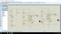
Hi have this circuit to make the two led blinking, however i want to put an emergency switch in, but when i put it after or before the BAT1 in the orange position, the leds keep blinking.I'm reading after the emergency switch is off always 5V and leds keep blinking.
Also when i cut the connections in the yellow line the leds continue to blink.
It is a software bug or is my mistake?
I would appreciate some help please.

Best regards
upload_2017-3-27_4-39-50.png
 

Attachments

WBahn

Joined Mar 31, 2012
30,072
Many logic simulators have inferred power rails for logic devices. For instance, look at your right-hand device -- there is no connection at all to the power rail, yet presumably it simulates. You need to look into your simulator's documentation to find out how to configure the power for IC devices.
 

Thread Starter

danabr87

Joined Jan 18, 2012
14
Yes, even when the right-hand device that as no connection, it keeps blinking, and in the VCC appears to have 5V. The simulator that i use is Proteus 8 Professional, do you know other simulators, to find out if it is the software that as something wrong?
 

EM Fields

Joined Jun 8, 2016
583
Yes, even when the right-hand device that as no connection, it keeps blinking, and in the VCC appears to have 5V. The simulator that i use is Proteus 8 Professional, do you know other simulators, to find out if it is the software that as something wrong?
Your circuit seems to be in order, and duplicating it in LTspice and running a simulation with Vcc disconnected from both astables yields:
Sim anomaly.png
So it appears, as WBahn noted, that you may need to configure your software to have it not supply Vcc to the 555's without a solid connection to Vcc,
 

absf

Joined Dec 29, 2010
1,968
I have the same problem too with my proteus. Even changing the Design/Config Power Rail/VCC to 0V wouldn't help...
:(:p

funny.PNG
Allen

[edit] oops I think I have connected C1 upside down. Hope there is no explosion on my screen.:D
 
Last edited:

absf

Joined Dec 29, 2010
1,968
No. In proteus all the TTL and CMOS logic chips have the Vcc, Vdd and Vss hidden. The Vcc is represented in the schematics by the icon like an "UP" arrow.

When using CMOS chips, you can have options of 5V, 10V and 15V for the Vcc in the device properties. By clicking on the device and change the Vcc for each device.

4011_1.PNG

But if you want to change the whole power rail from 5V to 9V or 10.5V. You will have to do a Marshall change on the "Design" Tab and change the whole power rail in one command.

4011_2.PNG 4011_3.PNG

Allen
 
Top