Trying to power an F56 BMW/MINI car instrument cluster.

Thread Starter

tychop

Joined May 26, 2017
3
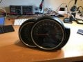
I bought an instrument cluster on ebay to try and send CANBUS signals to it.
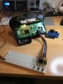
But I can't seem to get any life into it.. It's hooked up to a breadboard so I can easily put power on pins.
I tried connecting pin1 to power and pin7 to ground, but nothing 'lights up'...

It's about connector A71*1B on https://www.newtis.info/tisv2/a/en/...hicle-electrical-system/pt-can-bus/1VnXYfRERL

Does anybody have suggestions on how to power this thing up?
My guess is I have to do something to the wake-up signal in pin15.....
 

bwilliams60

Joined Nov 18, 2012
1,450
There should be a main battery feed, an ignition feed and ground just to get it lit up. Then you have illumination and depending on the gauge set, they can be controlled by sensors or CAN BUS signals. If you want speed and tach, you may need to simulate the car signals and again they can be on the bus. Just to light it up, you should not need the PCM or any sensors.
post a picture of the cluster and the connector bodies, perhaps I can help.
I believe you power 1 and 2 and ground 7 and 8
what year is this car?
 

Thread Starter

tychop

Joined May 26, 2017
3
My car is a 2015 MINI John Cooper Works. The Instrument Cluster is from a Cooper S model, but that doesn't matter. (Same hardware).
Pin 6 & 12 are CanBus high & low and the cluster receives it's values to display via that network.
I want to send my own values in a lab setup to the cluster and have it react to it. But first.... I need to power it on..

I tried to put power (12v) on 1 & 2 and grounded 7 & 8, but nothing happened..

After that I tried putting some power on the pin11 for the wake up signal, but I think the signal is probably not supposed to be +12v...

Here's the instrument cluster:IMG_0434 (1).jpg IMG_0436 (1).jpg
 

bwilliams60

Joined Nov 18, 2012
1,450
Hey Tychop, you are wading into uncharted territory for me. I am assuming you are in the UK as none of my Mitchell stuff has any information on this system. I am assuming that the wake-up would have a 12V temporary signal followed by communication on the CAN BUS to keep it awake. Do you know for sure this is a good cluster? Can you measure the signals on a MINI to see what happens when you tun the key on? I do cluster work so you have my interest. Keep in touch
 

yoda.bear

Joined Jun 5, 2017
11
Can you find a service manual on the vehicle? That may contain some of the electrical values you are looking for as far as what voltage the wake up signal is looking for.
 

SaleB

Joined Jul 3, 2017
7
I may be able to help out. A71*2B is connection to the audio/navigation unit. A71*3B is data connection to the HUD display. A71*1B is the main connection. Terminal 30 in automotive world means 12v always hot from the battery plus terminal. Terminal 15 is also 12v, but switched by the means of key position II. pin 10 is power for the HUD from the instrument cluster, and I assume is not needed. You will need 12v on p1, p2, p11 and grounds (in automotive terminology terminal 31), at p7 and p8. Temperature sensor p4 and p5 I assume are resistive inputs with maximum of 5v. From the information in the diagram, I see that p4 gets the red/yellow wire, and p5 white/green wire. I assume if there is only one temperature gauge inside the cluster, that p4 gets the 5v ref. voltage and the p5 the actual sensor voltage. If there are two temerature sensor inputs, then both wires will accept two 0-5v signals for two independent gauges. You can test the voltage on the cluster pins, and if any of these two pins has value 5v, assume that the other pin is sensor voltage input.

That leaves only CAN L and CAN H, about that I can only tell you that the cable should be terminated with 120 ohm resistors, but with the CAN massages for specific actions I cannot help
 
I bought an instrument cluster on ebay to try and send CANBUS signals to it.
But I can't seem to get any life into it.. It's hooked up to a breadboard so I can easily put power on pins.
I tried connecting pin1 to power and pin7 to ground, but nothing 'lights up'...

It's about connector A71*1B on https://www.newtis.info/tisv2/a/en/...hicle-electrical-system/pt-can-bus/1VnXYfRERL

Does anybody have suggestions on how to power this thing up?
My guess is I have to do something to the wake-up signal in pin15.....
Did you ever get it to work im trying to use this gauge in my R56
 
Top