Trying to make LED matrix, which will all light up together (no need for controlling individual leds). Preferably with single power source

Thread Starter

tashnag

Joined Jan 2, 2024
6
First photo is the intended goal.
Second photo is how I soldered it together
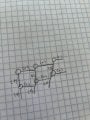
Third is my fake schematic (dont know how to read/write schematics)
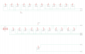
final photo is schematic from tinkercad (not sure if its accurate)

I want to make something for myself that looks like the first photo. Potentially using thousands of LEDs, and hope to figure out if my wiring makes sense, and if I can power with a single source, and how to calculate power requirements. I havent seen anyone wiring up LEDs this way, so not sure if there is an inherent flaw in my design to begin with.

Any help will be greatly appreciated.
 

Attachments

ThePanMan

Joined Mar 13, 2020
803
For starters you need to control the amperage going to each LED. For that you'd need an individual resistor for every LED. OR you can opt for a higher starting voltage and put three LED's in series using a single resistor to control the string. In theory you could put a whole bunch of LED's in series provided you have enough voltage to light the LED's.

Here's how an LED works: First, there's a forward voltage (Vf). That Vf needs to be subtracted from the voltage source. You used 9V as a source voltage so I'll stay in keeping with that. Suppose you have three LED's in series with 3.0Vf (different LED's will have a different Vf. That puts you right at 9V total so you don't really have a way of controlling the current other than the voltage source's internal resistance. You could end up with thousands of burned out LED's in a hurry. But let's suppose your LED's have 2Vf. (9V - 2Vf x 3) = 3V. That's just for starters. You have 3V headroom to work with. You'll need a resistor. But what resistor? You need to decide on what current you want these three LED's to run at. I'd recommend no more than 20mA (0.02A). So from this you have 3V ÷ 0.02A = 150Ω. A single 150Ω resistor will provide 20mA current through that string of 3 LED's. And the LED's will be happy. Now, if you want a thousand LED's, divided by 3 that's going to be 333 1/3 sets of LED's. Let's get rid of that single LED (the 1/3). You have 999 LED's in 333 strings of three LED's. That's also 333 resistors at 150Ω.

So 333 sets of LED's running at 20mA that's 6 2/3 amps.

An option easily enough attained is to use 12 volts as a source. Since white LED's tend to run around 3Vf (depending on the supplier) you'll have (12V - 9Vf) ÷ 0.02A = 150Ω. Looks like the same resistor for either circumstance. But you said you want to use WHITE LED's, that's likely around 3Vf per LED.

You COULD go with 24V and string 7 LED's in series, all with 3Vf. That's 21Vf. (24V - 21Vf) ÷ 0.02A = 150Ω. What's changing is the starting voltage and the number of LED's in the series string. BUT WAIT! THERE'S MORE. You are dissipating 3 volts through each resistor. 120mW through each resistor. Each resistor need a minimum of 1/8 watt capability. 1/8 watt is 125mW. Much too close to your working wattage. 1/4 watt would be better, but bigger. 120mW X 333 strings means dissipating about 40 watts of heat energy. That's not a small amount of heat. So a lot of your work is going to making heat.

Doable. But I don't think I'd undertake such a project. But that's me personally.

Good luck with your project.
 

Thread Starter

tashnag

Joined Jan 2, 2024
6
Thank you for the very well explained reply.

I would like to add some more information:

- I am trying to avoid stringing together 3 or even 7 leds each with its own resistor. 2 main reasons are: I dont want most of the electricity going to create head in all the resistors. Second I dont want all those resistors showing. I was hoping to use something like a voltage regulator to handle the job more efficiently. (again Im not proficient enough to know if this will work or if its practical).

- I am ASSUMING the way i have it set up is in a series (please tell me if this is correct).
- If it is in a series, how would I calculate the amount of voltage, watts, and mA required.
- I suppose then I can find out if its possible to light up with 1 power supply.
- If its not in a series, what is it?
- Then how would I calculate how to power it up, how many V, mA, Watts will I need the power supply.
- I wouldnt mind usingle multiple series's if it makes more sense to actually accomplish the task, but I am really just trying to figure it out.

It must be possible since this guy does it! https://www.jasonkrugman.com/capellaBasket/

Thank you!

For starters you need to control the amperage going to each LED. For that you'd need an individual resistor for every LED. OR you can opt for a higher starting voltage and put three LED's in series using a single resistor to control the string. In theory you could put a whole bunch of LED's in series provided you have enough voltage to light the LED's.

Here's how an LED works: First, there's a forward voltage (Vf). That Vf needs to be subtracted from the voltage source. You used 9V as a source voltage so I'll stay in keeping with that. Suppose you have three LED's in series with 3.0Vf (different LED's will have a different Vf. That puts you right at 9V total so you don't really have a way of controlling the current other than the voltage source's internal resistance. You could end up with thousands of burned out LED's in a hurry. But let's suppose your LED's have 2Vf. (9V - 2Vf x 3) = 3V. That's just for starters. You have 3V headroom to work with. You'll need a resistor. But what resistor? You need to decide on what current you want these three LED's to run at. I'd recommend no more than 20mA (0.02A). So from this you have 3V ÷ 0.02A = 150Ω. A single 150Ω resistor will provide 20mA current through that string of 3 LED's. And the LED's will be happy. Now, if you want a thousand LED's, divided by 3 that's going to be 333 1/3 sets of LED's. Let's get rid of that single LED (the 1/3). You have 999 LED's in 333 strings of three LED's. That's also 333 resistors at 150Ω.

So 333 sets of LED's running at 20mA that's 6 2/3 amps.

An option easily enough attained is to use 12 volts as a source. Since white LED's tend to run around 3Vf (depending on the supplier) you'll have (12V - 9Vf) ÷ 0.02A = 150Ω. Looks like the same resistor for either circumstance. But you said you want to use WHITE LED's, that's likely around 3Vf per LED.

You COULD go with 24V and string 7 LED's in series, all with 3Vf. That's 21Vf. (24V - 21Vf) ÷ 0.02A = 150Ω. What's changing is the starting voltage and the number of LED's in the series string. BUT WAIT! THERE'S MORE. You are dissipating 3 volts through each resistor. 120mW through each resistor. Each resistor need a minimum of 1/8 watt capability. 1/8 watt is 125mW. Much too close to your working wattage. 1/4 watt would be better, but bigger. 120mW X 333 strings means dissipating about 40 watts of heat energy. That's not a small amount of heat. So a lot of your work is going to making heat.

Doable. But I don't think I'd undertake such a project. But that's me personally.

Good luck with your project.
 
Tashnag,

You have a choice; serial or parallel.

If you hook them up in serial you will connect the LEDs together as a string. Don't forget that a LED is a diode so it's polarity sensitive. If the leads to the LEDs are different colours, no problem, just connect the black to the red (or similar) until they are all hooked together. Some LED lights have built in bridge rectifiers, in which case just hook them together, no colour code needed. Check to see: Use your multimeter to see if you get current through the bulbs in both directions. If yes, you have a bridge built in, if not, be careful to hook up the LEDs in the right order.

The downside to serial is that you need enough voltage so that, when it's divided by the number of LEDs you're hooking up, you have enough overall EMF to drive sufficient current through all the LEDs.

The alternative is parallel. Connect all the red leads together and all the black leads together and provide them with enough voltage to light any one of them and enough current to provide all of them with the current they need to light - at least visibly.

The disadvantage is that you can need a lot of current at little voltage and that can be expensive. The advantage is that you can add or subtract LEDs as you want.

Hooking them up isn't difficult, it's the power supplies that are the difficulty. Series is easier, higher voltage, lower current.

Hope this helps.

John
 

Thread Starter

tashnag

Joined Jan 2, 2024
6
Thank you for the help! Based on what you said, I'm assuming i have them in a series. I may have to go to parallel to keep the voltage low, but I dont know yet how that will look if Im trying to mimic jason krugmans lights pictured in the original post.

- If I do decide to go to parallel with low voltage and higher current, what power supplies do i look for?
- If i stick with them in a series and go with a higher voltage, is that going to be dangerous to touch if its all still exposed or it will still be ok?

Tashnag,

You have a choice; serial or parallel.

If you hook them up in serial you will connect the LEDs together as a string. Don't forget that a LED is a diode so it's polarity sensitive. If the leads to the LEDs are different colours, no problem, just connect the black to the red (or similar) until they are all hooked together. Some LED lights have built in bridge rectifiers, in which case just hook them together, no colour code needed. Check to see: Use your multimeter to see if you get current through the bulbs in both directions. If yes, you have a bridge built in, if not, be careful to hook up the LEDs in the right order.

The downside to serial is that you need enough voltage so that, when it's divided by the number of LEDs you're hooking up, you have enough overall EMF to drive sufficient current through all the LEDs.

The alternative is parallel. Connect all the red leads together and all the black leads together and provide them with enough voltage to light any one of them and enough current to provide all of them with the current they need to light - at least visibly.

The disadvantage is that you can need a lot of current at little voltage and that can be expensive. The advantage is that you can add or subtract LEDs as you want.

Hooking them up isn't difficult, it's the power supplies that are the difficulty. Series is easier, higher voltage, lower current.

Hope this helps.

John
 

ThePanMan

Joined Mar 13, 2020
803
I'm assuming i have them in a series. I may have to go to parallel to keep the voltage low, but I dont know yet how that will look if Im trying to mimic jason krugmans lights pictured in the original post.

- If I do decide to go to parallel with low voltage and higher current, what power supplies do i look for?
- If i stick with them in a series and go with a higher voltage, is that going to be dangerous to touch if its all still exposed or it will still be ok?
If you try to operate them at mains voltage you're creating a dangerous animal. Touch the wrong places and you're going to understand why I say that. Then there's line voltage fluctuation, meaning your LED's will be exposed to higher and lower voltages at different times. But voltage is not the main concern. LED's are current powered, not voltage powered. In theory you can power a single LED from 1KVDC as long as you have the appropriate resistor. Extreme as this example is - it is only meant to instruct you on the proper thinking when it comes to LED's. 5 to 25mA MAX is the maximum current you'd ever want to run an LED at. Your LED might survive 30, 35 even 40mA. For a short while that is. The higher the current the faster they burn out. Also, you are more subject to thermal run-away where they can get hot and become more susceptible to excess current. Even at low currents, thermal run-away can be a problem.

Powering LED's from mains voltage also has another issue; AC current. Even with the proper resistance and current that's only when the sine wave is going positive. When it goes negative the LED has to block all that voltage. Poof goes the LED. You'd need to rectify the AC to pulsed DC, full wave DC or full wave filtered DC. Filtering AC will result in 1.414 times the voltage over what the AC was. If you're running 12VAC, full wave rectified and filtered you'll have 16.97VDC. That can't be ignored. It'll be the death of your project if you don't account for that.

No, I wouldn't recommend mains powered LED's. Nor would I recommend running a series of LED's to eat up all the voltage. There's still no regulation. And just one LED goes out then power is interrupted to ALL OTHER LED's. Then you're going to have fun looking for that one in a thousand that has gone out. Series/Parallel is the way I'd go. Even if a series string were to go out I only have a few LED's to check and replace. The rest will remain unaffected. But it's your project. Just approach it smart and safe.
 

dl324

Joined Mar 30, 2015
17,228
Can you mark up IMG_7651 to indicate anode and cathode? Then I'll try to understand how you have the LEDs connected because your schematic isn't helpful at all.

This is partial schematic shows how I wired the LEDs in a 4x4x4 cube. It's arranged as a 2D matrix with 4 rows and 16 columns with a current limiting resistor per column. You can choose to drive the LEDs one at a time; I chose to do 4 at a time.
1704846414671.png
 

dl324

Joined Mar 30, 2015
17,228
I studied your connection photo and this is how I think you have the LEDs connected:
1704847442157.png
You shouldn't connect them that way because they'll all be on at the same time and there will be current hogging if the diodes don't have matched forward voltages.

With this configuration, you can turn the LEDs on by a row at a time, column at a time, or individually.
1704847805323.png
This circuit is set up to drive them by rows. To drive by columns the resistors would be on the rows and one column would be enabled at a time.
 
Last edited:

boostbuck

Joined Oct 5, 2017
577
It must be possible since this guy does it! https://www.jasonkrugman.com/capellaBasket/
When I look very carefully at that, I suspect the mesh of LEDs was a non-functioning model for a final much larger scale structure. It is described thus "...over 10,000 circuit boards distribute and deliver power to 1,860 LED light sources" which sounds as though each light is more complex than just a led, and the interconnections are some kind of pipe that probably contains several wires.
 

Sensacell

Joined Jun 19, 2012
3,510
Jason's art piece uses larger high powered lighting elements, I am sure each one has a current regulating element included.

All of these decisions are based on compromise, there is no one ideal way to do it.

1) Firstly- there is a "bottom line" power requirement - this is the Vf of the LED X the current, so for those small WHITE diodes @ 20 mA it's .064W or 64 mW for each lamp. (3.2V X 0.02A)
This represents the ideal, perfect scenario, regulating the current correctly always implies more losses.

2) The wiring has voltage drops, your drive must allow for these drops, which can be very significant as things get big.
Current flow causes these drops- series circuits keep the current lower, at the expense of higher voltages.

3) The maximum safe voltage - around 48V.


Looking inside the a modern mains powered LED fixture, you will always find long strings of series connected LED's, this yields the most efficient drive, but the total voltage can be hundreds of volts.
This is fine inside an enclosed product, but with exposed wiring, you need to keep the total voltage low,


I would make it strings of 12 LEDs in series, with a resistor on each string, running from 48V.
Connect multiple strings in parallel.

12 X 3.2 = 38.4 Volts, so the resistor drops ~ 10V - for 20 mA use 500 ohms. (1/4 W minimum)
Each string burns about 1 Watt. (48X 0.02)

You may be tempted to add more LED's to the string, but this 10V buffer gives you the headroom you need to absorb small voltage drops in the wiring without noticeable current variations.

Here is the Whitney museum in NYC clad in LED's I engineered this for the artist - Erwin Redl.

Matrix.png
 

Tonyr1084

Joined Sep 24, 2015
8,015
I find so many things worth repeating in the following quotes:
You shouldn't connect them that way because they'll all be on at the same time and there will be current hogging if the diodes don't have matched forward voltages.
Yes. Current hogging. I have a video of current hogging if you like. I can post it directly to you in a private chat.

with exposed wiring, you need to keep the total voltage low
From what I understand, the maximum voltage considered to be a "Low Voltage System" is 50 volts. 48 volts is within that realm. I've personally experienced the electrical sensation of touching what was 64VAC. It was due to cross talk and a bad ground. It didn't hurt or harm, but it's considered to be above the LVS regulations I believe I'm aware of.

this 10V buffer gives you the headroom you need to absorb small voltage drops in the wiring without noticeable current variations.
That headroom allows for current control. Taking three LED's with a 3Vf in series on a 9V source will light the LED's but you have no current control. The ONLY regulation for current on a 9V system with three 3Vf LED's is the power supply's internal resistance. You can take an LED and a CR2032 battery and connect the diode directly to that battery. The 3Vf LED will light but the battery's internal resistance will limit the amount of current that can flow. That's the reason why you don't want to dissipate all the voltage through the LED's because there's no way to control the current. Thermal runaway can occur.
 

ThePanMan

Joined Mar 13, 2020
803
This is the NEC:
United States
In electrical power distribution, the US National Electrical Code (NEC), NFPA 70, article 725 (2005), defines low distribution system voltage (LDSV) as 0 to 49 V..

The NFPA standard 79 article 6.4.1.1[4] defines distribution protected extra-low voltage (PELV) as nominal voltage of 30 Vrms or 60 V dc ripple-free for dry locations, and 6 Vrms or 15 V dc in all other cases.

Standard NFPA 70E, Article 130, 2021 Edition,[5] omits energized electrical conductors and circuit parts operating at less than 50 V from its safety requirements of work involving electrical hazards when an electrically safe work condition cannot be established.

UL standard 508A, article 43 (table 43.1) defines 0 to 20 V peak / 5 A or 20.1 to 42.4 V peak / 100 VA as low-voltage limited energy (LVLE) circuits.
 

Thread Starter

tashnag

Joined Jan 2, 2024
6
Jason's art piece uses larger high powered lighting elements, I am sure each one has a current regulating element included.

All of these decisions are based on compromise, there is no one ideal way to do it.

1) Firstly- there is a "bottom line" power requirement - this is the Vf of the LED X the current, so for those small WHITE diodes @ 20 mA it's .064W or 64 mW for each lamp. (3.2V X 0.02A)
This represents the ideal, perfect scenario, regulating the current correctly always implies more losses.

2) The wiring has voltage drops, your drive must allow for these drops, which can be very significant as things get big.
Current flow causes these drops- series circuits keep the current lower, at the expense of higher voltages.

3) The maximum safe voltage - around 48V.


Looking inside the a modern mains powered LED fixture, you will always find long strings of series connected LED's, this yields the most efficient drive, but the total voltage can be hundreds of volts.
This is fine inside an enclosed product, but with exposed wiring, you need to keep the total voltage low,


I would make it strings of 12 LEDs in series, with a resistor on each string, running from 48V.
Connect multiple strings in parallel.

12 X 3.2 = 38.4 Volts, so the resistor drops ~ 10V - for 20 mA use 500 ohms. (1/4 W minimum)
Each string burns about 1 Watt. (48X 0.02)

You may be tempted to add more LED's to the string, but this 10V buffer gives you the headroom you need to absorb small voltage drops in the wiring without noticeable current variations.

Here is the Whitney museum in NYC clad in LED's I engineered this for the artist - Erwin Redl.

View attachment 312323
I can not private message you. Can you start a conversation? I may not have enough permissions on this forum to start one yet.
 

Thread Starter

tashnag

Joined Jan 2, 2024
6
Just keep it public?
You need to reach a certain level of *something* before you can PM
I just think I need professional help with this. You mentioned you engineered that project for an artist. I was wondering how we can get in touch to see if you would be interested in engineering a project for me.

I do not mind asking many more questions, and hoping for answers, and doing more research, but this seems a little big to risk mistakes.

thanks, let me know!
 

Wendy

Joined Mar 24, 2008
23,492
You will find this site is a good place to learn electronics. As a tutor once told a future King, There is no royal road to math. LEDs are fun, I've burned out my share with various brain farts. But they were fun to abuse.
 
Top