trying to find a circuit to control a fail safe relay, 555 timer?

Hymie

Joined Mar 30, 2018
1,347
The random re-triggering will almost certainly be due to electrical noise from the switch action.
If this problem is being exhibited when testing the circuit (using a switch to trigger the timer), I suggest you test the circuit in final application, with the BMS providing the trigger signal and see how it performs.

If you Google ‘switch deboucing’ you will find various switch configurations to combat the effect. Probably the simplest is to place a capacitor across the switch contacts – adding impedance in the debounce circuit can improve things further (with the switching having the time constant of the circuit capacitor and impedance).
 

Thread Starter

Chipper

Joined Jul 19, 2018
60
The random re-triggering will almost certainly be due to electrical noise from the switch action.
If this problem is being exhibited when testing the circuit (using a switch to trigger the timer), I suggest you test the circuit in final application, with the BMS providing the trigger signal and see how it performs.

If you Google ‘switch deboucing’ you will find various switch configurations to combat the effect. Probably the simplest is to place a capacitor across the switch contacts – adding impedance in the debounce circuit can improve things further (with the switching having the time constant of the circuit capacitor and impedance).
actually i was simply touching the trigger wire to the power supply lead, no wonder there was noise. when i do this quickly and purposefully the random trigger seems to not occur. it will be a few days before i'm able to get the circuit in a position to test in situ. thanks again for all your help, you're brilliant c

PS When the shop heater kicked on a moment ago there was enough noise through the power supply to trigger, wow!
 
Last edited:

Hymie

Joined Mar 30, 2018
1,347
To minimise electrical noise affecting the circuit, the trigger input wiring/leads should be kept as short as possible and away from high voltage circuits where capacitive coupling could cause triggering.

Mains borne electrical noise from nearby equipment switching on/off is likely to be affecting the DC supply (resulting in circuit triggering). To harden the circuit against these effects, feed Vcc to the circuit via a diode with the addition of a 10uF in parallel with 0.01uF capacitor after the diode to 0V (the 10uF cap will protect against load variations within the circuit and the 0.01uF against fast transients/voltage spikes).
 

Thread Starter

Chipper

Joined Jul 19, 2018
60
To minimise electrical noise affecting the circuit, the trigger input wiring/leads should be kept as short as possible and away from high voltage circuits where capacitive coupling could cause triggering.

Mains borne electrical noise from nearby equipment switching on/off is likely to be affecting the DC supply (resulting in circuit triggering). To harden the circuit against these effects, feed Vcc to the circuit via a diode with the addition of a 10uF in parallel with 0.01uF capacitor after the diode to 0V (the 10uF cap will protect against load variations within the circuit and the 0.01uF against fast transients/voltage spikes).
Thanks for the tip Hymie, I'll incorporate the change in the final circuit. Am I correct in assuming the the trigger pin can remain at Vcc until pulled low to 0V?

One thought that may help me install this circuit.. Can keep trigger connected to 0V and activate the timer by connecting Vcc to a signal voltage of 14V? This would help me with the wiring install with the BMS and it seems it would reduce the current draw of the circuit and prolong battery charge when the charge mode is not active. This trigger method seems to work fine with the latest as built circuit, I'm just unsure of the long term results
 
Last edited:

Hymie

Joined Mar 30, 2018
1,347
The input should be at Vcc when not triggered, if left floating (or at a lower voltage) and then switched to 0V it may not trigger the timer.

If the BMS circuit that is switching low is say 5V and switched low to 0V, then you will need an additional transistor stage which switches the 13V to 0V, driven by the 5V logic circuit.
 

Thread Starter

Chipper

Joined Jul 19, 2018
60
The input should be at Vcc when not triggered, if left floating (or at a lower voltage) and then switched to 0V it may not trigger the timer.

If the BMS circuit that is switching low is say 5V and switched low to 0V, then you will need an additional transistor stage which switches the 13V to 0V, driven by the 5V logic circuit.
Let correct something I wrote earlier. My BMS charge enable stays ON (actually pulls to ground) when charging is allowed. So I'm facing a situation where my trigger signal is reverse of what will work my circuit. However it does have another multi-purpose enable that will pull to ground when I program it to in the event of a too high cell voltage in the battery.

Like this:


Maybe to clarify what I have now is a block of signal relays activated when the BMS sinks to ground (175ma max) the +V from my battery to pull the relays closed. This allows me to power various relays to handle the higher current loads of discharge and charging.. The need for the pulsed circuit I've been working on is to power a latching relay that tends to burn out if it gets a continuous power to both coils
 
Last edited:

Hymie

Joined Mar 30, 2018
1,347
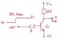
It is a very simple matter to add a single transistor to invert the BMS signal (as in the circuit below).

The transistor (Q1) can be almost any NPN low power device with the base resistor R chosen as 47KΩ, would only require minimal gain from the transistor for the circuit to operate correctly.
Transistor invert.jpg
 

Hymie

Joined Mar 30, 2018
1,347
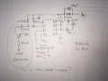
Yes, although you have omitted the collector 4k7 ohm reistor.

But you have misunderstood the location of the 10uF capacitor, which you have placed in parallel with the supply diode.

This 10uF should be in parallel with the 0.01uF capacitor to 0V.

And your diode across the relay coil is shown in the wrong polarity.
 

eetech00

Joined Jun 8, 2013
4,711
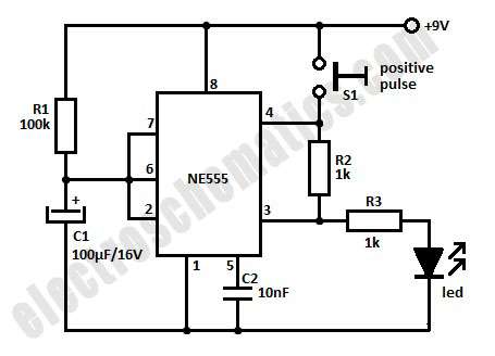
In terms of the timer circuit, this 555 timer circuit will do what you want; with the trigger input (pin 2) capacitively de-coupled such that should the trigger input remain low (longer than the timed period), the circuit will give a positive output pulse period, determined by the component values Rt & Ct.

With Rt = 91kΩ & Ct = 10uF will give a positive output pulse of circa 1 second.

View attachment 160912
Hi

Sorry for jumping in, but I noticed that the timing diagram in post #7 looks a little strange.

VCC is shown going low and triggering the circuit. But that can't happen if the supply voltage (VCC) is at 0v.:confused:
Nor can the output energize after timeout. :(

eT
 

Hymie

Joined Mar 30, 2018
1,347
The circuit was taken from my 555 timer cookbook.

I think that the input is shown at Vcc and going to 0V, and not implying that the supply voltage to the circuit is reduced to 0V (this was explained in the book’s narrative).

Perhaps the circuit would have been better if a pull-up resistor had been included at both sides of the capacitor (to Vcc) – with a switch shown triggering the timer.

As has been eluded to within some of my posts, the input needs to be at Vcc and taken low (to trigger the circuit), and not floating or at some lower voltage.

But you have a point, a novice building the circuit may believe that they need to drop the supply voltage to 0V to achieve the waveforms shown.
 

Thread Starter

Chipper

Joined Jul 19, 2018
60
The circuit was taken from my 555 timer cookbook.

I think that the input is shown at Vcc and going to 0V, and not implying that the supply voltage to the circuit is reduced to 0V (this was explained in the book’s narrative).

Perhaps the circuit would have been better if a pull-up resistor had been included at both sides of the capacitor (to Vcc) – with a switch shown triggering the timer.

As has been eluded to within some of my posts, the input needs to be at Vcc and taken low (to trigger the circuit), and not floating or at some lower voltage.

But you have a point, a novice building the circuit may believe that they need to drop the supply voltage to 0V to achieve the waveforms shown.
 

Thread Starter

Chipper

Joined Jul 19, 2018
60
Hymie, I just breadboarded the circuit and made the additions suggested, seems to work as advertised. I had the blocking diode built right but drew it wrong... next step is build a better looking board and install in the battery system. Watch a future post to this thread.. Thanks to you for all your help, and to all the others on this forum...goodnight for now. c
 

Hymie

Joined Mar 30, 2018
1,347
I look forward to the design of the proposed additional fail-safe monitoring circuit that will operate should the timer circuit have failed for some reason.
 
Top