 Facebook
 Google
 GitHub
 Linkedin
Hi,
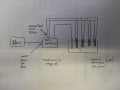
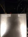
I am new to building circuits, and could use some help getting a project off the ground. I work in a lab and am trying to heat a reaction vessel to a desired temperature using an aluminum block, equipped with 4 heating cartridges (see attached image).
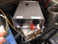
I already own a temperature controller that I can use with a commercial heater. The temperature controller receives input from the mains (label says AC input, 120V, 8A, 60Hz). It is hooked up to a thermocouple (Type J) which is inserted into my aluminum block heater, which provides temperature feedback to the temperature controller. The temperature controller, based on the temperature feedback, then provides power to four heating catrdiges (each are 600W, 5A). The heating cartridges are equally spaced around the aluminum block and are wired in parallel. The power cord I used to connect to my circuit is rated for 13A (which seems like it could be a little low).
When I turn the temperature controller on, it immediately blows the fuse within the controller. The fuse is rated 8A, 250 V. The commercial heater I own that actually works with this temperature controller says 500W, 115V on it.
I am wondering how I need to adjust my setup to have it work properly. It seems that perhaps my heating cartridges are trying to draw to much power from the controller? Unfortunately I do not know enough about this stuff to really work it out, but would be interested in learning.
If I can provide more information, please let me know. I have attached some pictures of the setup if that helps.
I am new to building circuits, and could use some help getting a project off the ground. I work in a lab and am trying to heat a reaction vessel to a desired temperature using an aluminum block, equipped with 4 heating cartridges (see attached image).
I already own a temperature controller that I can use with a commercial heater. The temperature controller receives input from the mains (label says AC input, 120V, 8A, 60Hz). It is hooked up to a thermocouple (Type J) which is inserted into my aluminum block heater, which provides temperature feedback to the temperature controller. The temperature controller, based on the temperature feedback, then provides power to four heating catrdiges (each are 600W, 5A). The heating cartridges are equally spaced around the aluminum block and are wired in parallel. The power cord I used to connect to my circuit is rated for 13A (which seems like it could be a little low).
When I turn the temperature controller on, it immediately blows the fuse within the controller. The fuse is rated 8A, 250 V. The commercial heater I own that actually works with this temperature controller says 500W, 115V on it.
I am wondering how I need to adjust my setup to have it work properly. It seems that perhaps my heating cartridges are trying to draw to much power from the controller? Unfortunately I do not know enough about this stuff to really work it out, but would be interested in learning.
If I can provide more information, please let me know. I have attached some pictures of the setup if that helps.
Attachments
-
 160.6 KB Views: 10
 -
 111.3 KB Views: 12
 -
 159.8 KB Views: 11
 -
 113.6 KB Views: 10


