Troubleshooting Of Servo Valve

Thread Starter

zobi92

Joined Feb 1, 2014
19
Hello,

Hope you guys are fine.

I have a card for servo hydraulic valve driver, but it is very old one, therefore I can't find it stuff on internet and I am very new to this.

For now, What type of signal it required? I mean to say either it required (+-5V 0-100mA) or something else.

I am uploading stuff of this so that you guys get better understand what I am trying to say.

Second, I am uploading it driver circuit diagram, please explain the circuit.

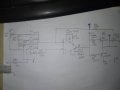
IMG_20190306_170502 : I have redrawn from the complete schematic because I think this one is driving my servo valve and I am trying to understand how this will produce output to drive valve. Pin 41,40,39 is input and pin32 is output
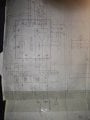
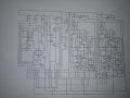
IMG_20190306_170938.jpg: This is the complete schematic of the driver card.
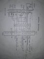
IMG_20190306_172318.jpg: This is the valve diagram.

Kindly guide me .
 

Attachments

mvas

Joined Jun 19, 2017
539
It looks like an Summing Inverting Op Amp design with a Closed Loop Gain = 15.
The output has a bipolar swing of +/- 15 Volts, so at Max Gain the Input can be as as low as +/-1 Volt
RV1, RV2 & RV3 are the Input Voltage Dividers that could allow +/- 5 Volts input.

Can you get an open circuit resistance measurement of ...
Pin 41 to RV1 wiper = ?
Pin 40 to RV2 wiper = ?
Pin 39 to RV3 wiper = ?
That would allow you to compute the Input Voltage Divide value.

Is Input Pin 38 used as an Input or No Connection ?
The input Signal is the SUM of Pins 38 + 39 + 40 + 41
Could Pin 38 be a Fixed Negative Voltage Offset, which then allows the Inputs to be: Zero to Positive vs Bipolar ?
 

MaxHeadRoom

Joined Jul 18, 2013
30,562
Generally this type of servo valve has a amplifier/driver that has a ±10vdc input.
With some kind of feed back component, either encoder or potentiometer etc.
What is the mechanism it is controlling?
Max.
 

MisterBill2

Joined Jan 23, 2018
27,186
The servo valve does not require that much drive current and so this could be the entire thing. Lots of symbols that I am not familiar with, though. Servo valves mostly need an amplifier when there is a feedback system in place. The feedback signal would come from either a pressure sensor, a load cell, or a position sensor, possibly a LVDT. The last servo valves that I worked with ran up to 20mA
Those three adjustments are attempts at integral gain, derivative gain, and proportional gain. It has been a long time since I worked with hydraulic servo amplifiers
 

Thread Starter

zobi92

Joined Feb 1, 2014
19
It looks like an Summing Inverting Op Amp design with a Closed Loop Gain = 15.
The output has a bipolar swing of +/- 15 Volts, so at Max Gain the Input can be as as low as +/-1 Volt
RV1, RV2 & RV3 are the Input Voltage Dividers that could allow +/- 5 Volts input.

Can you get an open circuit resistance measurement of ...
Pin 41 to RV1 wiper = ?
Pin 40 to RV2 wiper = ?
Pin 39 to RV3 wiper = ?
That would allow you to compute the Input Voltage Divide value.

Is Input Pin 38 used as an Input or No Connection ?
The input Signal is the SUM of Pins 38 + 39 + 40 + 41
Could Pin 38 be a Fixed Negative Voltage Offset, which then allows the Inputs to be: Zero to Positive vs Bipolar ?
Thanks for your reply.

Actually, customer has changed the resistance of Potentiometer, so it is not certain. But currently it is set on :
Pin41 to RV1 wiper = 1.1K
Pin40 to RV1 wiper = 4.4K
Pin39 to RV1 wiper = 3.4K

Input Pin38 is feedback from motor speed sensor input as mentioned in valve diagram. Let me upload one more picture it would make more clear to you, this is a block diagram of the PCB + J5(Connector for servo valve) . Please link this picture with valve diagram.
 

Attachments

Last edited:

Thread Starter

zobi92

Joined Feb 1, 2014
19
Generally this type of servo valve has a amplifier/driver that has a ±10vdc input.
With some kind of feed back component, either encoder or potentiometer etc.
What is the mechanism it is controlling?
Max.
Thanks for your reply.

Sir, it is getting a feedback from Pin38 which is described in Valve Diagram(Pin8 and Pin7) .
 

Thread Starter

zobi92

Joined Feb 1, 2014
19
The servo valve does not require that much drive current and so this could be the entire thing. Lots of symbols that I am not familiar with, though. Servo valves mostly need an amplifier when there is a feedback system in place. The feedback signal would come from either a pressure sensor, a load cell, or a position sensor, possibly a LVDT. The last servo valves that I worked with ran up to 20mA
Those three adjustments are attempts at integral gain, derivative gain, and proportional gain. It has been a long time since I worked with hydraulic servo amplifiers
Thanks for your reply.

Therefore, sir can you please tell, what type of signal you have provide for servo valve to operate in terms of voltage and current. And what type of signal it required to operate or how you operate.
 

MisterBill2

Joined Jan 23, 2018
27,186
Based on the circuit drawings it looks like the power supply for the servo amplifier board should be both +15 volts and -15 volts, along with the common connection. What I see then as the input control voltage would be 10 volts, either positive or negative, depending on which direction the load is desired to move. I think that you mentioned that the load was a hydraulic motor with a speed feedback, which is reasonable, those systems that I worked with the load was always a cylinder and the feedback was always the position of the cylinder, which is a bit different. So you may need to adjust the P, I, and D resistors to provide the performance that you seek. Those adjustments usually vary with the mechanical system being driven.
I hope that my explanation makes sense.
For really good explanations you could visit the websites of some of the servo-valve companies. The principles of operation are similar even if the products are different.
 
Top