Trouble powering multiple circuits from a single battery

ebp

Joined Feb 8, 2018
2,332
A snubber across the gear motor might help. Don't use just a capacitor as that can make things worse. Use a series combo of a capacitor, probably in the range of a few nF to 100 nF and low-value resistor in the range of 5 to 50 ohms. I'd start with about 10 nF and 20 ohms. Remember that if the motor is powered by unfiltered PWM, there will be a current pulse through the RC each time the driver turns on, so the impedance of the snubber should not be too low.

Get the conductors to the speed sensors twisted into proper groups.
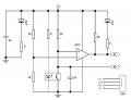
We need a schematic of the speed sensor boards.
 

Thread Starter

mikeoz

Joined Sep 25, 2017
86
ebp, thanks a lot for your help with this.

I'm quite new to electronics, when you say,
Get the conductors to the speed sensors twisted into proper groups.
Do you mean I should twist together the VCC and GND of each speed sensor - but not the DO (signal) cable?

The gearmotor C speed is controlled with PWM. Should I not use the 0.1uf ceramic capacitor across the motor terminals then? If I order a 10nf ceramic capacitor and a 20 Ohms resistor, could you take me through how I need to connect it to the circuit?

Finally, would this resistor and capacitor be ok?:

https://www.ebay.co.uk/itm/10-x-20-...sh=item19bf4ea03b:g:CaoAAMXQPd1RHkpC#shpCntId

https://www.ebay.co.uk/itm/50-x-10n...073517?hash=item4602d2b2ed:g:1H0AAOSwZjJU840h

Many thanks,

Michael
 

Thread Starter

mikeoz

Joined Sep 25, 2017
86
ebp: The IR sensors are LM393 FC-03 modules. The board schematic is attached below.

Well, I tried the 0.1uf ceramic capacitor I ordered across the gearmotor C terminals and also twisting the VCC & GND leads into pairs for each sensor module, it didn't make a difference sadly. If someone could explain how the 'snubber' should be connected, I'd like to try that. I can't move forward with this project until I can resolve this problem.

Michael
 

Attachments

Top