 Facebook
 Google
 GitHub
 Linkedin
Hello
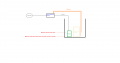
My dad asked me to make an automatic water pump activation device for our home pool. The main pool pump motor is housed in a 1,2 meter deep 'well'
and that well sometimes fills up after heavy rains so it's necessary to pump the water out before it reaches a certain height and starts damaging the main pool motor. I've got a pump which is made for this purpose but the issue is that it uses a float to detect the water level and does not trigger until the height is over 40cm which is way too much (I've already tried to think of ways how to modify it but it just doesn't work out). After consulting with a colleague we have come to a conclusion that the best option would be to use a triac and switch the pump from mains. This way no surgery/modification is required to the pump.
I have drawn an illustration of the setup. I know how I would make it trigger at the maximum allowed level but I don't know how to introduce hysteresis
to the system so that it keeps pumping until it reaches the lowest level. I've never used triacs.
The other idea that I had was to use a 'linear' feedback loop with a triac where the switching angle was proportional to the height of the water
but something tells me that water pumps won't work in a linear fashion.
The requirements are:
- Max water level : ~20 cm
- Min water level: ~7 cm
The pump runs at ~300W (Runs from mains AC plug)
I've got a triac that handles 800V 8A cont , ~60APeak
We've already come up with a semi solution but it's way too complicated. I know that it can somehow be cleverly done using
one triac and one or two transistors so if anyone has an idea let me know please. Thanks in advance.!
Attachments
-
 19.6 KB Views: 27


