Facebook
 Google
 GitHub
 Linkedin
Hello there!
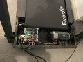
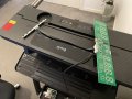
I'm trying to hack my functioning treadmill.
The unit is just terrible:
My idea is to control the speed with an Arduino to give it better control over the speed, define my own running programs and to be able to upload the stats (ESP32).
Specs:
Motor: Revo Drive M610 - 2.5HP, 4000 RPM, 180VDC
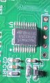
Controller Board: JFDZ_PBJ_XK_COMST_V2.20
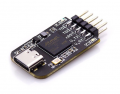
The display unit connects to the controller board through 5 pins with the codes V,T,R,G,S.
Initially I thought the S pin received the PWM signal so my idea was to dump the display unit and make the arduino control the PWN signals.
But it turns out the display unit maintain a serial communication with the controller board through the T and R pins and the S pin is not for PWM.
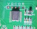
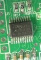
The display unit is ruled by a STM32 controller (32G030F6P6) and the controller board by a STM8S (8S003F3P6), and apparently they talk to each other about the motor speed and killer switch.
Without the T and R pins connected the display unit shows an error.
Without the S pin the display unit works properly but the motor doesn't turn.
I bought one of those cheap logic analysers on amazon - still waiting for the delivery - and I'll try to decode the serial signals with the hope that I'll be able to replicate them with the Arduino.
Plan B:
If dumping the display unit doesn't work, I'll try to control the buttons on the display unit and make the arduino "press" them programatically and internally calculate speed and distance.
Does anyone knows about the STM controllers and how to decode them?
Or any other idea how to accomplish this without buying another expensive controller board?
Thanks in advance
I'm trying to hack my functioning treadmill.
The unit is just terrible:
- There are 14 speeds, one button cycles through 3,6,9 and 12.
- The - and + buttons increase the speed by 0.1 increments.
- The predefined programs are bad.
- As soon as you finish your run, you have no data about the session, it just turns off.
My idea is to control the speed with an Arduino to give it better control over the speed, define my own running programs and to be able to upload the stats (ESP32).
Specs:
Motor: Revo Drive M610 - 2.5HP, 4000 RPM, 180VDC
Controller Board: JFDZ_PBJ_XK_COMST_V2.20
The display unit connects to the controller board through 5 pins with the codes V,T,R,G,S.
Initially I thought the S pin received the PWM signal so my idea was to dump the display unit and make the arduino control the PWN signals.
But it turns out the display unit maintain a serial communication with the controller board through the T and R pins and the S pin is not for PWM.
The display unit is ruled by a STM32 controller (32G030F6P6) and the controller board by a STM8S (8S003F3P6), and apparently they talk to each other about the motor speed and killer switch.
Without the T and R pins connected the display unit shows an error.
Without the S pin the display unit works properly but the motor doesn't turn.
I bought one of those cheap logic analysers on amazon - still waiting for the delivery - and I'll try to decode the serial signals with the hope that I'll be able to replicate them with the Arduino.
Plan B:
If dumping the display unit doesn't work, I'll try to control the buttons on the display unit and make the arduino "press" them programatically and internally calculate speed and distance.
Does anyone knows about the STM controllers and how to decode them?
Or any other idea how to accomplish this without buying another expensive controller board?
Thanks in advance
Attachments
-
 134.6 KB Views: 22
 -
 3.4 MB Views: 23
 -
 178.5 KB Views: 20
 -
 2.6 MB Views: 19