Treadmill control board component ID

Thread Starter

Ed627

Joined Nov 13, 2014
22
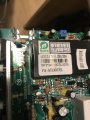
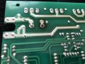
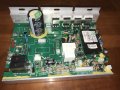
Hi All, We have a Sole F63 treadmill and the motor control board has quit due to increased load on the motor from a worn belt. I could use some help identifying a component on the board that looks to be melted on one end.

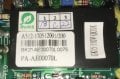
In the pictures below it’s the larger rectangular black component with the white stickers on the top. Measures about 1-1/4” by 2-1/4”. There’s no printing on the sides or under the stickers and they seem to relate to the board and not the component.

It’s in position U2 and has two rows of 7 pins along each long edge underneath and two pins at the end closest to the heat sink.

Would love to be able to fix this board as new ones are expensive. Any input would be appreciated, thanks!
 

Attachments

MaxHeadRoom

Joined Jul 18, 2013
28,619
If it was a increased load that caused the problem I would tend to think it may be more like one of the semi's on the heat sink.
Max.
 

wayneh

Joined Sep 9, 2010
17,496
The part you’re asking about is probably proprietary. It’ll be hard or impossible to find, possibly more expensive than a replacement board, and difficult to swap out even if you did find one.

The good news is, I’m with Max: I think it’s unlikely that’s the failed part. One of those transistors on the heat sink may have roasted.
 

Thread Starter

Ed627

Joined Nov 13, 2014
22
Thanks for the replies. I was afraid it might be proprietary.

I was hoping the same thing about the chips on the heat sink (two are ultrafast diode chips and two closest to that chip are mosfets) until I saw the deformed end of the big chip that looks melting. I’ll post a pic below.

But now that you mention it, given that the melting is on the heat sink end, is there any chance those two mosfets got hot enough to cause that end of the proprietary chip to deform and maybe it is ok? The insulation jacket on the female disconnect that’s on the end of the red wire that goes to the motor looks like it got hot so there was a fair amount of current being called for by the motor under load. The male blade connector that it plugs into on the board also looks like it got hot.

Checked the motor today with an 18v batt and all seems good. Also replaced the walking belt and much less friction.
 

Attachments

Thread Starter

Ed627

Joined Nov 13, 2014
22
I should add that the board is mounted vertically so the proprietary chip is just above the heat sink chips when the board is in place.
 

Ya’akov

Joined Jan 27, 2019
9,071
I am guessing that damage is from the shunt adjacent to it. Now that doesn’t mean there isn’t internal damage to the potted circuit. It reminds me of DC-DC converters, but the pin count is excessive for that. However its size would tend to suggest it has to dissipate some heat.

Maybe you could find some “non-working” boards cheap and hope you get some good parts for substitution. Of course we have no way to know if your failure mode is the norm or unusual.
 

MaxHeadRoom

Joined Jul 18, 2013
28,619
You could remove the power semi's and check them, they should not cost that much to pick them up from Digikey.
That was my guess also that the heat on the unit was from some other source, also there could also be a component internally that is getting warm but not the cause of the failure.
Max.
 

Thread Starter

Ed627

Joined Nov 13, 2014
22
Good point on the failure mode. This is our second board since buying the treadmill new in 2014 and they’re both the same design. I googled the board number to see what a replacement would go for and the pictures show boards with that component missing so it was possibly redesigned.

Yeah at this point I think it’s worth testing those heat sink components and seeing if they’re bad. There are also 2 components on the bottom of the board with long leads that allow them to contact the metal base and use it as a heat sink. One is a bridge rectifier but there’s no visible number on the other one. (both are square with 4 long leads) In addition to the parts in question, are there any others I should also remove and test? Thanks for the assistance so far, sincerely appreciated!
 

Attachments

MaxHeadRoom

Joined Jul 18, 2013
28,619
You could apply power to the board and see if you get output from the bridge rectifier.
After I would start with checking the semi's on the H.S.
Max.
 

Thread Starter

Ed627

Joined Nov 13, 2014
22
Checked both the original board and the newer one. Rectifier isn’t working on the old board but on the new one it was a slow climb to 143 VDC so that looks to be working.

Anything else I should check before I pull the mosfets off and test them? Is it possible that they’re the only isssue or do other parts tend to go bad in this type of high load failure?
 

MaxHeadRoom

Joined Jul 18, 2013
28,619
Check the AC side of the bridge on the old board, if AC is present, it may be worth trying a new bridge.
Anything that appears that it is involved in motor power is a good candidate for testing.
I am not familiar with those particular boards, but unusual to see the DC climb slowly.
Max.
 

Thread Starter

Ed627

Joined Nov 13, 2014
22
Thanks Max. AC is present and I also figure it’s worth trying a new rectifier in the old board. Be nice to have a back up if I can get both working.

I was surprised it was a slow rise too but there’s a big capacitor next to the rectifier and I figured that may be why, but just a guess.

This board also has a transformer connected to it and is responsible for controlling the incline motor and I suspect the fans in the console so I’ll see if I can sort out what components are for the drive motor and remove and test those.
 

pfofit

Joined Nov 29, 2006
57
Unless your input voltage is 100VAC , your bridge may be half-waving or the cap has crapped out and is not doing its job resulting in too much AC ripple on your DC source. MAy be why it is low and rising slow.

What is your VAC input voltage?
 

Thread Starter

Ed627

Joined Nov 13, 2014
22
VAC at the connectors on the board is 118V. Across the rectifier it’s the same as the DC, starts at about 70V and is a slow climb to about 114V.

If I disconnect the capacitor and check it with the DVM on the capacitance setting is that a valid check?
 

pfofit

Joined Nov 29, 2006
57
If I disconnect the capacitor and check it with the DVM on the capacitance setting is that a valid check?
Maybe, depending on the meter and if the cap is really bad, but a good reading of capacitance on DVM would not be definitive proof of a good cap. There are other parameters together that determine a good cap.

Is there anything in the path from the 118VAc leading to the bridge terminals, like a resistor or NTC disc?
Do the + and - of the bridge go direct to the cap?
I would check for ac ripple on the cap or I would be checking the bridge on diode check. All 4 diodes both ways.
If you have the heak sink off, show an aerial pic of top and bottom of board so all components can be seen.
index.jpg
 

Thread Starter

Ed627

Joined Nov 13, 2014
22
One leg of the line power goes right to the bridge rectifier. The other goes to the switched leads of a relay (JQX-105F-1) before it goes to the bridge and that relay doesn’t get activated when power is applied to the board. But across those relay leads are a 22uF cap in series with a 10 ohm resistor. I suspect this is why it takes time for the voltage to rise. I could jump out the relay and confirm.

The large 1500 uF cap is connected directly to the output leads of the bridge.

Here are the pics you asked for. In front of the 2 FETs on the top right of the board there’s a thick metal jumper (RT1) and on the bottom of the board one of the connections for that jumper is blackened so it looks like it got hot. I’ll include 2 pics of that also.
 

Attachments

MaxHeadRoom

Joined Jul 18, 2013
28,619
If it is across the coil then it is a snubber, if across a pair of contacts then you are reading the AC into the bridge through these components, with a high impedance meter you will read a slowly building DC.
Max..
 

Thread Starter

Ed627

Joined Nov 13, 2014
22
Yeah it’s across the contacts, it says on the coil housing that the coil is 12VDC and I found a data sheet that seems to confirm this. So that would explain the rising DC readings.

My next plan is to desolder the FETs, Bridge rectifiers, and test them to see which are bad, unless there’s something else I should test while the board is still intact?
 
Top