Nothing shows up, it appears the board has a custom microcontroller, very unusual for a T.M. board.
If you try the resistor it is not much of a loss if it blows again, I would test those large semi's for short.
Max.
Hello, well i had a play about with this board , i checked the mosfets they seam to working ok , i replaced the blown resistor, cap and varistor. powered up no pops or bangs so a big smile was across my face... but after trying run the motor nothing happened , now for the strange thing the motor works (as i have tested it on a dc 18 volt supply) at the circuit board were the motor goes to my multi-meter reading is 180v ??
now is it that the volts can be still 180v but no current to drive the motor or am i missing something with looking too hard at this
Cheers
Mal
Is this , 180v, with the motor connected?
If you have the motor connected and measure 180v on the actual leads to the motor, the motor would/should take off!
Max.
Is this , 180v, with the motor connected?
If you have the motor connected and measure 180v on the actual leads to the motor, the motor would/should take off!
Max.
Hiya , am sorry i had another look today but the volts i got today was 70v without motor on and also 70v with motor on with no motor movement at all.
I am almost 100% that it was 180v yesterday ??? (honest i hadn't had a drink either . )
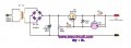
hiya . Well i had another look today as this voltage was puzzling me ... After i checked the voltage again it was 180v ?, I found out where it's coming from (school boy error) i turned off the main supply and the volts was still there then after a little while it started dropping . mmmm then bells ringing in my head , the volts are coming from the capacitor . Am pretty sure they shouldn't be there are they ??? (as the control panel as a error 1 on it preventing me to start the motor) am thinking would it be easier to make one from scratch ?? i have seen this circuit witch look pretty straight forward to make .. would it be ok to power my 180v 4amp 4300 rpm motor , or what will i need to change ?
Cheers Mal
Have you noticed the small print in the linked circuit in post #28? That supply is for 100mA max, so is unsuitable for your motor. As Max says, go with PWM. For safety's sake you will probably want a soft-start feature.
That is not a very efficient circuit IMO you would be better off with one of the PWM versions.
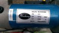
That is quite a small motor for a T.M.
Max.
Cheers Alec for spotting that (more heads are better than one ) . ,i will sort parts out and make a PWM version . I also thought it was a small motor ?? but apparently when it worked in the treadmill it was a powerfully motor , so i was told . thanks for your help and advice i will let you know what happens once it's been built and tested.
Cheers
Mal
If replacing the obviously dead components doesn't get it up, it would probably be quicker to find another one that works. That resistor didn't blow for no reason...
These treadmill PWM controllers are speed limited via a feedback loop, using either a magnet or an optical system and unless this feedback loop is in place, the motor will not spin up, it will start, then stop and go into fault mode. Hope that helps
Just a note on the replacement components: The resistor is DEFINITELY too small (looks like a quarter watt resistor)(and what was once there may be a one watt) but all I can do is guess as to their ratings.
I'm thinking the reason for the blow is someone wanted to see if they could resist the treadmill for as long as possible. Chances are they just overloaded the circuit.
I DO know those tread motors are typically 130 VDC motors, (not AC) typically rated at 2 1/2 HP. They vary in horse power but are typically around 2 HP or more.
I have a board and motor driving my bandsaw. The original 3/4 HP motor went bad. Faced with the cost of $180 to replace it I decided to give it a whack with the variable speed DC motor and controller board "From A Treadmill." I've torn several treadmills apart and have junked a lot of motors. One motor I hooked up to a lawn mower engine, however, the mower could only run about 3500 RPM max and the treadmill motor RPM was much higher at 130 VDC. The motor has a permanent magnet inside, so it can double as a DC generator. Best I got was about 60 VDC. Since it didn't give me what I wanted I just sold the project and let someone else mess with it. I hear the gasoline engine is now serving to power a go-cart. Oh well.
Check on Craig's List. I've seen plenty of those things being given away. Chances are good you can get a working variable supply to power any DC motor. Just keep in mind the DC voltages can reach upwards of 130 VDC. There's a potential for harm if not careful.
These treadmill PWM controllers are speed limited via a feedback loop, using either a magnet or an optical system and unless this feedback loop is in place, the motor will not spin up, it will start, then stop and go into fault mode. Hope that helps
I've been using these systems without the feedback feature on a bandsaw. When I bind the blade with a heavier load the motor seems to compensate. I don't know how they're doing that but I bet it has to do with the burned out resistor on our friends project. Sorry, but I disagree with you when you say there's a feedback loop that's needed to make the motor run. However, I'm not the expert on this; there can be other types out there that actually do depend on a feedback. Still, I think it should run.
Hiya all. Thank you for the info, well i replaced the blown parts and i checked some other parts which i thought could be at fault, but to no avail
so my new project is to attempt to make one from scratch i will try dodgydave's one first as i will have most if not not all the parts in stock . i will keep you posted
Cheers Mal
Hi All,
Well, I've looked thru my piles and see nothing similar to this, but I can surmise that the cap that vaporized and that resistor reside in what is called a "Snubber" circuit, which looks to be connected to the hot (+) side of the motor tab to the Switching FET right near the spot where C1 used to be.
This snubber or RC network tries to dampen switching spikes during the fast on/off switching of the main motor FET. Treadmill motors are driven with a square-wave and not a DC voltage level as most assume. This constant frequency, usually around 20-27khz, drive to the motor increases or decreases it's speeds dependent on the Duty-Cycle of the drive frequency supplied to that motor FET. For example, a slow speed means the controller is sending ON pulses at 20khz, at a Duty-Cycle or ON-Time, of say 10%.....then at fast speeds, that Duty-Cycle gets expanded to up to 95% at that same 20khz frequency, resulting in the motor seeing a larger DC source and spinning faster.
** Most all motor controllers have HOT Grounds on the motors power rail, and are NOT the same circuit grounds as the dc going to the console or operator controls which are required to be isolated for safety. You should NOT read 180vdc at the motor without a valid control, is the fet good?
** I also see folks mentioning that motor controllers are easy things, and I assure you there are many internal checks and balances to ensure before that motor turns one inch. Controllers monitor voltages, currents, phase corrections(3-ph), multiple feedbacks like a roller and encoder among other factors to keep these machines running safely, and no, it's not magic, it takes years of intensive learning and thinking to design these well.
I would make a stab at these values something in the order of .0047uf at 250v for that cap and a (correction)higher resistor of a couple hundred k-ohms, say 150-220kohm 2w, but this would be if that resistor and capacitor are in series with no other connections at it's intersection-connection, this is important. If there are any other traces to that interconnect point, there are other circuits to consider. Check that FET and DIODE for integrity, and check for a 22ohm to 200ohm resistor driving that FET Gate to make sure that resistor is ok.... You can always contact Fitness Remedy for help with fitness electronics.
Good Luck!
Treadmill motors are driven with a square-wave and not a DC voltage level as most assume. This constant frequency, usually around 20-27khz, drive to the motor increases or decreases it's speeds dependent on the Duty-Cycle of the drive frequency supplied to that motor FET.
Interesting. I never considered duty cycle. You're right, I assumed it was a DC voltage.
While the motor WILL run on 12 vdc (albeit very slowly), frequency control may be the key to why the motor does not appear to have a feedback loop. Every DC motor I've messed with has one black wire (negative), one red wire (positive) and two blue wires which are connected to a thermal switch. If the motor gets too hot the thermal switch opens.
I think I'll be pulling one of these boards out of the closet and power it up. Jatinah: What's the large coil choke for? At best I assume it's to block AC.
I am proud to see the "light" go on upstairs, opens the mind to all possibilities ;o) I should clarify a bit...
You are correct, DC motors will have a red and black lead, and sometimes the resetting thermal fuse you have in yours(blue wires), which will indeed cut out at about 170c and if allowed to cool, (entire motor now radiates heat and cooling takes an hour) will reset into it's short-like normal mode.
DC motors are not really frequency dependent except for the windings total Inductance "Q" during design(limits the switching rate to avoid saturations of the core). The motor inductance is a critical factor in designing motors and controllers. It is the "main" load we are manipulating, maintaining, regulating, watching, tweaking(on the fly in real time), for safe operation.
The LARGE COIL, or inductor you find inside treadmills with a DC motor is an added "Inductance". This added Inductance or "xL" (x of L, impedence of an inductive load) or coil now adds more "current response" for the driving motor and here's how this is done....
We switch a heavy FET(HEXFET, MOSFET, TrenchFET) at 20khz say,...now if you can imagine the switch operation on it's first several times of "turning off, then on, then off, then on" or switching, we nearly immediately build up a large volume of something called "Magnetic Flux", delicious hey?
This large area of flux eminates from the coil and surrounds it during times there is current passing thru the coil, or the FET "on" time(t1-on).
When this FET turns off, the motor, which in itself is a large coil allowed to spin, would quickly drain the current supply and the user would feel a sluggish feel to the unit with lose regulations. To avoid this, that coil imparts it's FLUX in the form of electrical current during the Off-times of the FET.
This helps to provide a sturdy motor movement and helps the motor with it's current needs. This is usually limited to DC motors as most AC motors take much less current. Clear as mud? Look up Inductance in Motor Control Design for a real boring explanation ;o)
Remember, the controllers usually need a pwm(pulse-width-modulated) input drive signal like the icon boards MC2100 series, Johnsons analog units and most other makers. Then there are sometimes an enable to allow motor rail power via a safety relay or SCR(pass element), and some also incorporate braking, which is removing that "Magic FLUX" and disallowing it's buildup will hold a motor rotor rock still!
For fun, spin the motor with wires left loose....easy hey?
Now tie the red to the black and try to spin that same motor....not so easy? Have a great day!
jatinah
 Facebook
 Google
 GitHub
 Linkedin
 ... but after trying run the motor nothing happened