Transistors basics.......

Thread Starter

Zeeus

Joined Apr 17, 2019
616
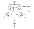
Hi..Made a similar circuit to the image : Inputs were not grounded...I used collector resistors at first so could position Vout dc (1/2 of supply) but after adding wilson mirror at the top : ...... big R : clip at top since Vout is close to V- (yh?)

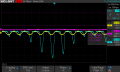
Yellow = difference signal purple = common signal(was about 100mv)

How to fix this?

Also https://forum.allaboutcircuits.com/threads/high-gain-from-a-bjt-ce-amp-with-no-bypass-cap.117823/

what's the function of q3 and q4 (5th to last post on page 1)...Thanks
 

Attachments

Jony130

Joined Feb 17, 2009
5,488
There is no surprise that your circuit does not work as you have expected. This diff amplifier with a current mirror load works well inside an integrated circuit. Where transistors are matched to each other. But instead, you have used a discrete transistor without any emitter degeneration resistor and do not provide any path for a differential current to flow.
Also, the diff amplifier stays in "linear region" only if the difference between the two base voltages is less than 30mV.

Did you read anything about the working principle of a diff-amp? Did you understand it?
https://wiki.analog.com/university/courses/electronics/text/chapter-12
 

Thread Starter

Zeeus

Joined Apr 17, 2019
616
. But instead, you have used a discrete transistor without any emitter degeneration resistor and do not provide any path for a differential current to flow.
I had 150 ohm at the emitters then connected to current source..."path for differential current to flow"??
Also, the diff amplifier stays in "linear region" only if the difference between the two base voltages is less than 30mV.
hmmm, don't understand? I tried at first with collector resistors and it seemed to work (attached image)

Did you read anything about the working principle of a diff-amp? Did you understand it?
https://wiki.analog.com/university/courses/electronics/text/chapter-12
lol..ofcos I read something! understood a little but still on it today...Thanks for the link

i do not understand function of q3 and q4 here..seems you do
https://forum.allaboutcircuits.com/threads/high-gain-from-a-bjt-ce-amp-with-no-bypass-cap.117823/
 

Attachments

Jony130

Joined Feb 17, 2009
5,488
I had 150 ohm at the emitters then connected to current source
You should add 150R resistor into the current mirrors emitters also.
But even this won't fix the main issue with the circuit.
"path for differential current to flow"??
I should say " you do not provide any path for a difference in current (Ic1 - Ic2) to go somewhere".
Try to think a little bit about this and what is goin on in the circuit.

Without the current mirror (with collector resistors) as a name suggest the differential amplifier "react" on a voltage difference between two bases.

\(\frac{Ie1}{Ie2} = e^{\frac{Vbe1- Vbe2}{26mV}}\)

If we assumed that if Vbe1 - Vbe2 = 0V we have Ic1 = 1mA and Ic2 = 1mA.

Also notice that Vdff = Vbe1 + Veb2 (from KVL loop). And this means that as Vbe1 increase Vbe2 must decrease by the same amount.

Therefore if Vbe1 > Vbe2 the Ic1 increase and Ic2 decreases by the same amount.

For example, if Ic1 rise from 1mA to 1.2mA at the same time the Ic2 current must decreases from 1mA to 0.8mA.
As you can see as long as you have any voltage difference between the two bases the collector's currents will also be different.
But the resistor at the collector does not care about it.
As you can see the diff-amp based on the voltage difference between two bases "steer" the tail current between one side (Q1) or to the other side (Q2).

But the situations changes when you are trying to "put" the current mirror at the collector. What current mirror does?
Current mirror "repeats" the current (mirror-it) at the output, in our cases, the current mirror tries to repeats the Ic1 current into Q2 collector.

Do you see the problem?

Let us exam the same situation Vbe1 > Vbe2. And because of this difference in voltage diff-amp wants to have a different current at each of the collector (Ic1 = 1.2mA and Ic2 = 0.8mA). But the current mirror will "repeat" Ic1= 1.2mA current to the other side (Q2). But the other side wants a different current (0.8mA). If you provide a path for the difference between what a current mirror is saying and what a diff-amp wants (Id = 1.2mA - 0.8mA = 0.4mA), then the circuit will work.
diff_amp12.PNG


https://electronics.stackexchange.c...e-av-value-with-current-sources/333536#333536

But you did not provide a path for this additional current. Not good. And the result of this situation you already know.
 
Top