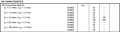
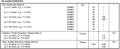
For the beta values, note that they specify a minimum Vce of 1V:
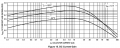
The reason being that at low Vce, beta falls off:
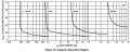
Just copied the first reasonable looking graph from the web. I presume the yellow shaded region is for saturation mode and the bluish is for active mode.
For the beta values, note that they specify a minimum Vce of 1V: View attachment 170506
The reason being that at low Vce, beta falls off:
Just copied the first reasonable looking graph from the web. I presume the yellow shaded region is for saturation mode and the bluish is for active mode.
A little transistor is not saturated when its collector to emitter voltage is as high as 1V.
hFE (beta) is used in an amplifying transistor that is never saturated.
Graphs on a datasheet are for a "typical" transistor that you cannot buy. Some transistors have minimum written specs and other transistors have maximum specs even if they have the same part number.
A little transistor is not saturated when its collector to emitter voltage is as high as 1V.
hFE (beta) is used in an amplifying transistor that is never saturated.
Graphs on a datasheet are for a "typical" transistor that you cannot buy. Some transistors have minimum written specs and other transistors have maximum specs even if they have the same part number.
Some transistors are more typical than others, and some are less typical, while on the average they are mostly typical. I think that Bob Pease once said that.
I design all my circuits so they work perfectly when a transistor has minimum or maximum spec's, not just "typical" spec's.
Then I do not need to buy thousands of transistors and test them to find the "typical" ones.
When using a transistor as a switch, you can make several assumptions that do not depend on the transistors characteristics.
First, ignore hfe. Use a β of 10. Second, while you can use Vbe on the datasheet, use a value of 0.7V.
The only variable is Iload. For example, if you run an LED with a Vf = 2V at 12mA and Vcc of 5V? then your base resistor must limit the current to 1/10th of Iload. Or in the example, 1.2mA.
Need to be careful making blanket statements like that. Power transistors are often used as switches -- it's in these applications that the benefits of operating in hard saturation are most pronounced. Power transistors have much lower hfe to begin with, particularly PNP transistors. Some of them have a hard time achieving β of 10 even when NOT in saturation. The 2n3055 (from ON Semi) is only guaranteed to have a β of 5 at an Ic of 10 A and a Vce of 4 V. The data sheets often use a β of 3 for these.
Second, while you can use Vce on the datasheet, use a value of 0.07V.
Why would you use 70 mV for Vcesat? Where is that number coming from?
If you are going to use that, why not just use zero?
Again, power transistors can have significantly higher Vcesat values, particularly PNP transistors operating at higher currents. The 2n3055 and 2n2955 can be as high at Vce = 1.5 V with β of 10 at Ic = 4 A and Vce = 3 V with β of 3 at Ic = 10 A.
The Vbe can be much higher, too. For these transistors, they can be up in the 1.5 V to even 2.0 V range.
I just learned recently that BC547, and some other BC* transistors, are spec'ed for a beta of 20 for saturation mode operation. And we know that TIP120 type darlingtons use 250.
Some try to use 20 for general purpose transistors like 2N3904, but I think that's pushing it a bit.
Need to be careful making blanket statements like that. Power transistors are often used as switches -- it's in these applications that the benefits of operating in hard saturation are most pronounced. Power transistors have much lower hfe to begin with, particularly PNP transistors. Some of them have a hard time achieving β of 10 even when NOT in saturation. The 2n3055 (from ON Semi) is only guaranteed to have a β of 5 at an Ic of 10 A and a Vce of 4 V. The data sheets often use a β of 3 for these.
Why would you use 70 mV for Vcesat? Where is that number coming from?
If you are going to use that, why not just use zero?
Again, power transistors can have significantly higher Vcesat values, particularly PNP transistors operating at higher currents. The 2n3055 and 2n2955 can be as high at Vce = 1.5 V with β of 10 at Ic = 4 A and Vce = 3 V with β of 3 at Ic = 10 A.
The Vbe can be much higher, too. For these transistors, they can be up in the 1.5 V to even 2.0 V range.
For saturation mode, you use 10 regardless of current. All of the other beta values are for operation in active mode. As I noted earlier, beta falls off steeply at low Vce.
Take some time to learn how to read a datasheet. Most, if not all, of the information you need will be there.
This table clearly states that the beta value you referenced is for Vce of at least 1V.
This graph gives a pictorial view of how beta changes with current:
This graph shows that the Ic/Ib ratio is constant at 10:
And shows the rise in Vce when base current is insufficient to saturate the transistor.
That value of 30 is the minimum value of hFE when Ic = 100 mA and Vce = 1.0 V.
The device is NOT in saturation, it is still in the active region.
When using the device as a switch, you normally want to drive it well into saturation (unless you need fast switching, in which case you want to stay just outside of saturation, but that doesn't seem to be the case here).
For most transistors of this type, the convention (and that's really all it is) is that the device is considered to be "well into saturation" when the hFE has dropped to about 10 or less.
So the normal process is to assume you will drive it into saturation and estimate the expected Vce under those conditions. For transistors of this type, Vcesat is usually in the 200 mV to 300 mV range. Often times, for quick design calculations, it is assumed to be zero.
Then figure out what the collector current will be when Vce = Vcesat. Then divide that by 10 to get the needed base current. Then assume that the Vbe is somewhere around 0.6 V to 0.7 V (the higher is usually the better from a margin-for-error standpoint). Then design your base drive circuit to deliver at least that amount of current.

 Facebook
 Google
 GitHub
 Linkedin