 Facebook
 Google
 GitHub
 Linkedin
Dear all
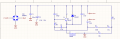
I have designed a circuit for cold mist generation using 1.7Mhz piezoelectric. the system works as spectated but the problem is that by drawing 400mA transistor gets hot after some minuets with a 23*30mm heat sink and some times it burns out and I could not understand why!! Any suggestion to protect transistor or all system improvement?
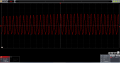
Attached is the schematic and voltage measurement at points "pizzo out +" and "pizzo out -". Also the test input DC voltage is after rectifier bridge is 34VDC and it draw 400mA.
Regards,
Mas
I have designed a circuit for cold mist generation using 1.7Mhz piezoelectric. the system works as spectated but the problem is that by drawing 400mA transistor gets hot after some minuets with a 23*30mm heat sink and some times it burns out and I could not understand why!! Any suggestion to protect transistor or all system improvement?
Attached is the schematic and voltage measurement at points "pizzo out +" and "pizzo out -". Also the test input DC voltage is after rectifier bridge is 34VDC and it draw 400mA.
Regards,
Mas
Attachments
-
 28.9 KB Views: 55
 -
 163.1 KB Views: 46


