 Facebook
 Google
 GitHub
 Linkedin
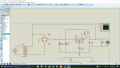
Hi all! im making this DC current power supply and i use a TIP120 to increase current but it gets overheat even if i use a heatsink...
the alternator is 110 AC volts and the transformer is 24V
the alternator is 110 AC volts and the transformer is 24V
Attachments
-
 149.7 KB Views: 39


")


