Transistor in an alarm circuit

Thread Starter

AlwaysNumber1

Joined Dec 4, 2016
52
Hi everyone !

I am new in the sphere of electronics and have just began to construct my circuits

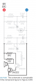
Have a question about the following small alarm system:
Why do we put this bipolar transistor with its collector to a loudspeaker ? How does it help us in any way ?
With my logic the transistor should be put with its emitter to amplify current

Will be happy to receive any help from you !
 

Attachments

LesJones

Joined Jan 8, 2017
4,190
Putting the load in series with the emitter only gives current gain. When the load is in the collector circuit it provides both current and voltage gain.

Les.
 

Thread Starter

AlwaysNumber1

Joined Dec 4, 2016
52
Putting the load in series with the emitter only gives current gain. When the load is in the collector circuit it provides both current and voltage gain.

Les.
Thanks a lot ?

But does it give the amplification at th collector already ?
I thought that it only happens at the emitter
 

LesJones

Joined Jan 8, 2017
4,190
To try to explin it fully you would need to provide the full shematic. It is a reasonable assumption that it will be a low impedance speaker so that only current amplification was required so the signal across the speaker would be almost the same if it was connected between the emitter and ground as it is connected in the collector circuit.

Les.
 

TheButtonThief

Joined Feb 26, 2011
237
Assuming you're using a speaker driver, it's a passive device that's voltage driven, it doesn't matter if the voltage is pulled to ground (like in the diagram you've supplied) or if it's... Actually, we can't even tell as we can't see the whole circuit. The 100r resistor, does get fed from the supply or does that connect to Gnd?
 

Thread Starter

AlwaysNumber1

Joined Dec 4, 2016
52
Assuming you're using a speaker driver, it's a passive device that's voltage driven, it doesn't matter if the voltage is pulled to ground (like in the diagram you've supplied) or if it's... Actually, we can't even tell as we can't see the whole circuit. The 100r resistor, does get fed from the supply or does that connect to Gnd?
Here is the whole circuit)
 

Attachments

Thread Starter

AlwaysNumber1

Joined Dec 4, 2016
52
To try to explin it fully you would need to provide the full shematic. It is a reasonable assumption that it will be a low impedance speaker so that only current amplification was required so the signal across the speaker would be almost the same if it was connected between the emitter and ground as it is connected in the collector circuit.

Les.
See the circuit above)
 

TheButtonThief

Joined Feb 26, 2011
237
Ahh right, there's 2! It looks like a pretty simple oscillator and 2-stage amplifier. Judging by the value of that ceramic capacitor (0.0047uF), the speaker will produce quite a high pitch sound. The first transistor is used to detect the tiny oscillation and turn it into a discernible signal, the second one will give some proper amplification.

Still, it would work the same if the speaker driver was on the emitter but those resistors would need to stay where they are as the 2k2 resistor is limiting current to the base of the second transistor and the 100r resistor is stopping the 2k2 resistor from shorting.
 

Thread Starter

AlwaysNumber1

Joined Dec 4, 2016
52
Ahh right, there's 2! It looks like a pretty simple oscillator and 2-stage amplifier. Judging by the value of that ceramic capacitor (0.0047uF), the speaker will produce quite a high pitch sound. The first transistor is used to detect the tiny oscillation and turn it into a discernible signal, the second one will give some proper amplification.

Still, it would work the same if the speaker driver was on the emitter but those resistors would need to stay where they are as the 2k2 resistor is limiting current to the base of the second transistor and the 100r resistor is stopping the 2k2 resistor from shorting.
But won't connecting speaker to the emitter give also voltage gain, while the collector will give only current gain ?
 
Top