Transistor Controlling 28 volts

Thread Starter

Rcflyer2552

Joined Jan 18, 2015
1
Hello,
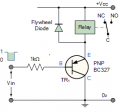
I am trying to get a circuit where a PNP transitor will control a 28 volt Relay when the base is grounded, will the BC327bu that is pictured in this schematic work with this?
Thank you
 

Attachments

Reloadron

Joined Jan 15, 2015
7,515
Yeah, the BC327 will work as drawn. Just keep the relay coil current below the max current the BC327 can handle (800 mA). I would look for a relay coil requiring 500 mA or less. Anyway, yes, for a PNP transistor that is what you want and when the base is at 0 volts the transistor will be On.

Ron
 

ScottWang

Joined Aug 23, 2012
7,398
The thing seems not that simple, if the input voltage of high is too low then you can't turn off the transistor, it also can't turn off the relay.
How is the input voltage, high low signal, a switch switching from high to low or some others?
I'm not sure why you want to using a low to drive the transistor when the relay is 28V, maybe you can change to NPN.
 

ronv

Joined Nov 12, 2008
3,770
I see what is bothering Scott. If the input is like 0 to 5 volts it won't turn off. If it is 0 to 28 all is well.
Guess we need to ask. What is the input signal???
 

ScottWang

Joined Aug 23, 2012
7,398
I see what is bothering Scott. If the input is like 0 to 5 volts it won't turn off. If it is 0 to 28 all is well.
Guess we need to ask. What is the input signal???
Yes.
And I'm trying to suggest him if the input needs to using low to drive, maybe he can using two bjts as the first is pnp and second is npn.
 

GopherT

Joined Nov 23, 2012
8,009
An NPN transistor should be used BC337 or BC338, 2N2222 etc. the BC327 is PNP and turns on when the input value is 0.6v Lowe than the emitter voltage. The PNP will not turn off in this configuration with this input.
 

Reloadron

Joined Jan 15, 2015
7,515
I believe the circuit the original poster has posted came from The Relay Switch Circuit which is just a collection of basic assorted transistors turning relays on and off. The link merely shows basic circuits without regard to component values. Here is what is stated pertaining to the circuit:

The PNP transistor circuit works in opposite to the NPN relay switching circuit. Load current flows from the Emitter to the Collector when the Base is forward biased with a voltage that is more negative than that at the Emitter. For the relays load current to flow through the Emitter to the Collector, both the Base and the Collector must be negative in respect to the Emitter.

In other words, when Vin is HIGH the PNP transistor is switched “OFF” and so too is the relay coil. When Vin is LOW, the Base voltage is less than the Emitter voltage, (more negative) and the PNP transistor turns “ON”. The Base resistor value sets the Base current, which sets the Collector current that drives the relay coil.

PNP transistor switches can be used when the switching signal is the reverse for an NPN transistor, for example the output of a CMOS NAND gate or other such logic device. A CMOS logic output has the drive strength at logic 0 to sink sufficient current to turn the PNP transistor “ON”. Then current sinks can be turned into current sources by using PNP transistors and a power supply of opposite polarity.
Ron
 
Top