Issue with PIC controlling Transistor.

Thread Starter

SirGr3mlin

Joined Jun 13, 2018
7
Hi there guys, im still wrapping my head around electronics and transistors and such.
I have a project im working on.
I prototyped it on a breadboard and it worked perfectly. but.. i did a rookie move and didnt test with the LM78L05 in circuit.
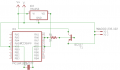
I want to drive a 12v buzzer in a project.
In the example below, the pic is turning RA0 on and off. when its off my plan was to have the transistor turn on.
then when its on turn the transistor off again. But i found once i put the LM78L05 in circuit the transistor would only stay on.
I feel i might be missing something.. I did try using a PNP transistor in which then switches the NPN on and off and that worked. but is there a better way than having 2 transistors?

Thanks for the help.
 

Attachments

ericgibbs

Joined Jan 29, 2010
18,849
hi SG,
Welcome to AAC.
A BC557 is a PNP transistor, it requires a negative collector voltage.

E
A NPN transistor is required, connect the Base via a 470R resistor to the MCU output pin.
Emitter to 0V and the Collector to your load.

EDIT:
Option.
how.png
 
Last edited:

Thread Starter

SirGr3mlin

Joined Jun 13, 2018
7
Hi E, thanks for the reply and the welcome, and not calling me and idiot ;-)
so wait what?... ... everytime i think in understand transistors i find them confusing me again. so... Nope im lost.
 

ericgibbs

Joined Jan 29, 2010
18,849
hi SG,
Which bit do you have a problem with, we are here to help.
Ask questions, but always give as much background info as possible. eg: details of the buzzer, voltage etc. value of the +v supply.
E
 

Thread Starter

SirGr3mlin

Joined Jun 13, 2018
7
The supply is 12v, I didnt see your edit and pic before i replied, the buzzer has an LED indicator that is switched on separately. the are linked together via Negative, meaning i have to switch the positive going to the buzzer and led separately.
 

ericgibbs

Joined Jan 29, 2010
18,849
hi,
Is it an old style electro-mechanical buzzer or the more common 'beeper' type buzzer.
Even though one end of the buzzer and LED are linked, you could still use the simple circuit I posted.
Do you have a circuit diagram showing the LED and buzzer.?

E
EDIT: Modify this drawing to suit your components
ESP1 13-Jun-18 14.28.gif
 
Last edited:

MrChips

Joined Oct 2, 2009
30,806
What you need to know is the difference between a low-side switch and a high-side switch.

upload_2018-6-13_9-29-27.jpeg

Generally, when we think of controlling the power to a device, we immediately think of a high-side switch, i.e. we switch the power line going to the load. The switching transistor can go in either position, on the low-side or on the high-side.


In the example shown, an N-channel MOSFET is used as a low-side switch, while a P-channel MOSFET is on the high-side. Because of the way the circuit performs, the control signals at the gate of the MOSFET are not the same in the two cases. One difference to note here is that a logic-high is required to turn ON the low-side driver.

To keep this discussion short, it is less problematic to put the transistor on the low side. This is the most common method used.
 

Thread Starter

SirGr3mlin

Joined Jun 13, 2018
7
Hey all thanks for your help, i ended up just chucking a BC547 that goes out to a 2N4403, im going to revisit the circuit at a later date. but apart from a stray wire burning out the PIC everything seems to work with this configuration. I set it up on a breadboard first and tested it but, let me know if you see anything wrong with this:


Bordodynov

Joined May 20, 2015
3,180
There is an alternative way of containing only one item - a control gate driver. It can be controlled by TTL levels. Choosing inverting or non-inverting, you can connect the zoomer to the supply voltage or earth. There are small drivers.
 

Thread Starter

SirGr3mlin

Joined Jun 13, 2018
7
I have ordered some p-Channel mosfets to
There is an alternative way of containing only one item - a control gate driver. It can be controlled by TTL levels. Choosing inverting or non-inverting, you can connect the zoomer to the supply voltage or earth. There are small drivers.
I have done a bit of googling, is there a link you can share because im getting all sorts of hits here.
 

MrChips

Joined Oct 2, 2009
30,806
I have ordered some p-Channel mosfets to

I have done a bit of googling, is there a link you can share because im getting all sorts of hits here.
As I said, it is more common to use an N-channel MOSFET. The N-channel MOSFET or NPN transistor switch goes on the low-side.
 
Top