 Facebook
 Google
 GitHub
 Linkedin
Hi,
at the moment I'm trying to build an IoT control circuit for an air condition based on an ESP32.
So far I have decoded the IR signal and using IR I can already control the AC.
The goal is to integrate it into AC to also be able to read out the LED status and receive and decode the signal if the IR remote control is used.
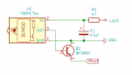
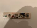
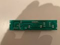
There is a small board containing the LEDs and the IR receiver which is attached via plug to the main board.
So I would like to put my circuit between those two boards so that I do not have to change or solder anything directly on the boards but have it plug and play and can remove or replace it easily.
I attached two photos of the small board containing the IR receiver, the schematic of the IR receiving part of this board (at least as I understood it and hopefully didn't get anything wrong there) and also the schematic of my first attempt of a circuit to attach the ESP32.
I think I'm already pretty close with my circuit but still it doesn't work.
I'm a very beginner and could need some help there and I'm grateful for any advise.
Also I think that I might have to add some pull-up and/or pull-down resistors but I'm not quite sure about that.
br,
Stefan
at the moment I'm trying to build an IoT control circuit for an air condition based on an ESP32.
So far I have decoded the IR signal and using IR I can already control the AC.
The goal is to integrate it into AC to also be able to read out the LED status and receive and decode the signal if the IR remote control is used.
There is a small board containing the LEDs and the IR receiver which is attached via plug to the main board.
So I would like to put my circuit between those two boards so that I do not have to change or solder anything directly on the boards but have it plug and play and can remove or replace it easily.
I attached two photos of the small board containing the IR receiver, the schematic of the IR receiving part of this board (at least as I understood it and hopefully didn't get anything wrong there) and also the schematic of my first attempt of a circuit to attach the ESP32.
I think I'm already pretty close with my circuit but still it doesn't work.
I'm a very beginner and could need some help there and I'm grateful for any advise.
Also I think that I might have to add some pull-up and/or pull-down resistors but I'm not quite sure about that.
br,
Stefan
Attachments
-
 30 KB Views: 13
 -
 37.6 KB Views: 13
 -
 82.8 KB Views: 13
 -
 76.4 KB Views: 10


