 Facebook
 Google
 GitHub
 Linkedin
Disclaimer - I'm learning!
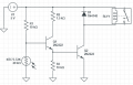
I need a 5V circuit which will control my relay. I've been trying to learn from the many examples on the net, but there are so many variations and almost none explain why/how they sized their components. Below is the 2-transistor circuit which makes the most sense to me, however I do not know how to determine the required sizes of R1, R2, and R3. The variable in my circuit is the thermistor, with a range of 5K to 72K. I would like the circuit to switch my relay ON when this thermistor hits 29K or greater. From the data sheet, my 5V relay coil has a resistance of 167ohms and a power rating of 150mW. I believe the transistors and diode are garden variety general purpose.
I would greatly appreciate a lesson in resistor selection/calculation for this circuit. Many thanks! Mike
Attachments
-
 23.5 KB Views: 4
")


