Facebook
 Google
 GitHub
 Linkedin
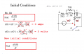
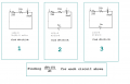
It looks like 20v/s is correct if the switch opens the 30v source and the 5 Ohm resistor as well as connecting the cap to the 25 Ohm resistor. That's dv(0+)/dt, and dv(0-) would be different.I will get back to your points later. Do you think the lastline of this transform is correct? this is about second order circuit/
View attachment 339217
The only question is what exactly do they want you to calculate. The article is titled "Initial conditions", and it appears you calculated v(0-) and i(0-) but then you calculated dv(0+)/dt. They asked for v(0), i(0), dv(0)/dt, and di(0)/dt, without specifying the just before or just after t=0 point in time.