Transient analysis - Dependent sources

Thread Starter

linhvn

Joined Nov 6, 2024
297
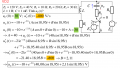
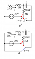
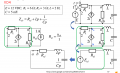
I am working on transient analysis , when it comes to find the characteristic equation , the book says just turn off independent sources, not mention to dependent sources, so I do not know how to deal with dependent source, like the circuit below, how to deal with dependent current source

1735145485785.jpeg
 

MrAl

Joined Jun 17, 2014
13,673
it is not quite right?!, I see the author transform but I don't understand why. the picture below, step 2 to step 3
View attachment 338946
Hello there,

If this was an exercise for a student then I would have to hope that this is not one of their first circuits and they would have more or less mastered circuit analysis by then.

I think the key here is the initial conditions of L and C, especially of L. Do you know how to calculate the initial conditions for L and C given circuit #1 ?
 

Thread Starter

linhvn

Joined Nov 6, 2024
297
Hello there,

If this was an exercise for a student then I would have to hope that this is not one of their first circuits and they would have more or less mastered circuit analysis by then.

I think the key here is the initial conditions of L and C, especially of L. Do you know how to calculate the initial conditions for L and C given circuit #1 ?
yes, they have more complex examples but I get stuck at this progress. Initial conditions already determined, just the step of transform the circuit to find characteristic equation is unknown yet.
 

Thread Starter

linhvn

Joined Nov 6, 2024
297
Hello there,

If this was an exercise for a student then I would have to hope that this is not one of their first circuits and they would have more or less mastered circuit analysis by then.

I think the key here is the initial conditions of L and C, especially of L. Do you know how to calculate the initial conditions for L and C given circuit #1 ?
I still don't understand the roots of this, initial condition has results, see green one and yellow one
1735290406252.png
 

MrAl

Joined Jun 17, 2014
13,673
I still don't understand the roots of this, initial condition has results, see green one and yellow one
View attachment 339007
Hello again,

1. Can you show more detail about how you came up with -800v/s ? That does not look right.
2. Also, you might also show more detail about how you came up with your Uc expression.

In #1 above, keep in mind that you may have it right (see later note below).

In #2 above, I assume you are using the general form but it's not clear how you came up with those numbers. You should elaborate. Hopefully you can keep it neat so it's easy to read.

[LATER]
Ok -800v/s may or may not be right (don't want to point out what might be wrong) but the final result is wrong, but there is a simpler reason for that.
 
Last edited:

Thread Starter

linhvn

Joined Nov 6, 2024
297
Hello again,

1. Can you show more detail about how you came up with -800v/s ? That does not look right.
2. Also, you might also show more detail about how you came up with your Uc expression.

In #1 above, keep in mind that you may have it right (see later note below).

In #2 above, I assume you are using the general form but it's not clear how you came up with those numbers. You should elaborate. Hopefully you can keep it neat so it's easy to read.

[LATER]
Ok -800v/s may or may not be right (don't want to point out what might be wrong) but the final result is wrong, but there is a simpler reason for that.
1, Just apply KVL in 2 loops like the circuit below, then we have 2 equations for 2 loops. It is complicated, I am not sure it is clear to you
View attachment 1735357118206.jpeg
View attachment 1735357135421.jpeg
The last line I caculated i2(0+) = -0.8 then U'c(0+) = -800V/s.
0+ means right after switch activated, 0- means right before switch activated.
 

Thread Starter

linhvn

Joined Nov 6, 2024
297
Hello again,

1. Can you show more detail about how you came up with -800v/s ? That does not look right.
2. Also, you might also show more detail about how you came up with your Uc expression.

In #1 above, keep in mind that you may have it right (see later note below).

In #2 above, I assume you are using the general form but it's not clear how you came up with those numbers. You should elaborate. Hopefully you can keep it neat so it's easy to read.

[LATER]
Ok -800v/s may or may not be right (don't want to point out what might be wrong) but the final result is wrong, but there is a simpler reason for that.
the final result is not wrong, if t ---> infinity, then Uc reaches steady state.
 

MrAl

Joined Jun 17, 2014
13,673
the final result is not wrong, if t ---> infinity, then Uc reaches steady state.
Hi,

Well, I could ask that if you were so sure it was correct then why ask the question :)

I am talking about the last line in post #6, the final expression for Uc(t).

At t=0 your result is 30 volts (as indicated by your calculation lines before that last line) and at t-->inf the result is -10 volts. I am sure you must agree with that.
Now look at the details surrounding the capacitor "C" in the schematic: the direction the voltage arrow for Uc is pointing.

I didn't want to insist that -800v/s was incorrect because you can actually calculate everything that way and I think it's easier that way, but you have to remember that so that when you come up with the final result you can write out the final result in the correct form. To be perfectly accurate though -800v/s is correct if you want to calculate everything that way, but not correct if you intend to apply it to the actual schematic given in the same way that you *must* apply the final result to the schematic given.

Does this make sense now?
 

Thread Starter

linhvn

Joined Nov 6, 2024
297
Hi,

Well, I could ask that if you were so sure it was correct then why ask the question :)

I am talking about the last line in post #6, the final expression for Uc(t).

At t=0 your result is 30 volts (as indicated by your calculation lines before that last line) and at t-->inf the result is -10 volts. I am sure you must agree with that.
Now look at the details surrounding the capacitor "C" in the schematic: the direction the voltage arrow for Uc is pointing.

I didn't want to insist that -800v/s was incorrect because you can actually calculate everything that way and I think it's easier that way, but you have to remember that so that when you come up with the final result you can write out the final result in the correct form. To be perfectly accurate though -800v/s is correct if you want to calculate everything that way, but not correct if you intend to apply it to the actual schematic given in the same way that you *must* apply the final result to the schematic given.

Does this make sense now?
The last equation U(c), you just replace t = 0, e(^-0) = 1, you got the same result, the rest of your paragraph I don't really understand what you mean, it is too lengthy and not direct to your points
 

Thread Starter

linhvn

Joined Nov 6, 2024
297
Hi,

Well, I could ask that if you were so sure it was correct then why ask the question :)

I am talking about the last line in post #6, the final expression for Uc(t).

At t=0 your result is 30 volts (as indicated by your calculation lines before that last line) and at t-->inf the result is -10 volts. I am sure you must agree with that.
Now look at the details surrounding the capacitor "C" in the schematic: the direction the voltage arrow for Uc is pointing.

I didn't want to insist that -800v/s was incorrect because you can actually calculate everything that way and I think it's easier that way, but you have to remember that so that when you come up with the final result you can write out the final result in the correct form. To be perfectly accurate though -800v/s is correct if you want to calculate everything that way, but not correct if you intend to apply it to the actual schematic given in the same way that you *must* apply the final result to the schematic given.

Does this make sense now?
I recalculate and as per my logic thoughts and from other lessons, it gives the same result as the professors made, What I want to know here is how they can come up with that solution or what the roots are behind that solution?
 

MrAl

Joined Jun 17, 2014
13,673
I recalculate and as per my logic thoughts and from other lessons, it gives the same result as the professors made, What I want to know here is how they can come up with that solution or what the roots are behind that solution?
Hello again,

The key to the problem ONLY involves the orientation of the arrow drawn to the right of the capacitor on the original schematic. Pay strict attention to that arrow and the way it points relative to the capacitor image.

The solution in the last line of your post is the solution *IF* the arrow to the right of the capacitor was turned 180 degrees so that the tip of the arrow pointed upward (see blue arrow in the attachment), not downward. You see the other sources the arrow points up and that means the positive terminal is at the top.
Note I've marked all the sources and the capacitor voltage with plus + and minus - marks to make it more clear. The cap voltage is marked with a red plus sign and red minus sign. Note that I did not correct any of the expressions.

The arrow indicates the way you measure the quantity. If you were to use a volt meter, you would place the positive (usually red) probe at the terminal marked by the tip of the arrow (the arrowhead) which is positive (+), then the negative probe (black) would go to the negative (-) lead which is the tail of the arrowhead.

If anyone else got the same answer you got in that last line, then they did not observe the correct polarity indicated by the arrow that was drawn to the right of the capacitor either. By doing that, they effectively multiplied all the results (including the derivative) by minus 1 (-1).

To get the right final result (for that schematic) you would have to multiply your results by -1.

In the attachment I have drawn a blue arrow to the left of the capacitor, and if the schematic was drawn with the arrow drawn like that then your final solution would be correct. It was not drawn like that however it was drawn with the arrow to the right of the capacitor which points downward. Surely you can see the difference. One way the cap voltage is of one polarity, and the other way it is of the opposite polarity. One way it will measure positive, and the other way it will measure negative.
As mentioned above, if you were to measure this with a voltmeter you would have to get the orientation of the two probes correct.

This schematic bothered me right from the start. The voltage sources were drawn like voltage controlled current sources not like the typical voltage source, but it seems apparent that they were to be interpreted as constant voltage sources. Since that is unusual, I have to wonder if they got mixed up with the arrow orientation for the capacitor voltage.
Flip the arrow and your final result is correct, don't flip it and you have to multiply everything by -1.

I do realize that you can calculate everything exactly the way you did from the first line to the next to last line. If you want to present the correct result though for the final expression, you then have to multiply the last result by -1.

Do you now see the difference that capacitor arrow makes in the final result ?
 

Attachments

Thread Starter

linhvn

Joined Nov 6, 2024
297
Hello again,

The key to the problem ONLY involves the orientation of the arrow drawn to the right of the capacitor on the original schematic. Pay strict attention to that arrow and the way it points relative to the capacitor image.

The solution in the last line of your post is the solution *IF* the arrow to the right of the capacitor was turned 180 degrees so that the tip of the arrow pointed upward (see blue arrow in the attachment), not downward. You see the other sources the arrow points up and that means the positive terminal is at the top.
Note I've marked all the sources and the capacitor voltage with plus + and minus - marks to make it more clear. The cap voltage is marked with a red plus sign and red minus sign. Note that I did not correct any of the expressions.

The arrow indicates the way you measure the quantity. If you were to use a volt meter, you would place the positive (usually red) probe at the terminal marked by the tip of the arrow (the arrowhead) which is positive (+), then the negative probe (black) would go to the negative (-) lead which is the tail of the arrowhead.

If anyone else got the same answer you got in that last line, then they did not observe the correct polarity indicated by the arrow that was drawn to the right of the capacitor either. By doing that, they effectively multiplied all the results (including the derivative) by minus 1 (-1).

To get the right final result (for that schematic) you would have to multiply your results by -1.

In the attachment I have drawn a blue arrow to the left of the capacitor, and if the schematic was drawn with the arrow drawn like that then your final solution would be correct. It was not drawn like that however it was drawn with the arrow to the right of the capacitor which points downward. Surely you can see the difference. One way the cap voltage is of one polarity, and the other way it is of the opposite polarity. One way it will measure positive, and the other way it will measure negative.
As mentioned above, if you were to measure this with a voltmeter you would have to get the orientation of the two probes correct.

This schematic bothered me right from the start. The voltage sources were drawn like voltage controlled current sources not like the typical voltage source, but it seems apparent that they were to be interpreted as constant voltage sources. Since that is unusual, I have to wonder if they got mixed up with the arrow orientation for the capacitor voltage.
Flip the arrow and your final result is correct, don't flip it and you have to multiply everything by -1.

I do realize that you can calculate everything exactly the way you did from the first line to the next to last line. If you want to present the correct result though for the final expression, you then have to multiply the last result by -1.

Do you now see the difference that capacitor arrow makes in the final result ?
Do you like contact in private, it is too lengthy and not direct to the points if typing
 

MrAl

Joined Jun 17, 2014
13,673
Do you like contact in private, it is too lengthy and not direct to the points if typing
Sure you can PM me any time.

This is not that complicated though, it's just a matter of how to interpret the arrow to the right of the capacitor in the original schematic. Pointing UP means the top is more positive than the bottom, and Pointing DOWN means the bottom is more positive than the top. If you were using a volt meter to measure this, you would swap the leads and get a negative reading, swap them again and get a positive reading.

I would do it the same way you did it, except at the end I would just multiply the final equation by minus 1 (-1).
So if I got say Uc=A*t then I would change it to Uc=-A*t. If I got Uc=-A*t then I would change it to Uc=A*t.

So we can say you did it right, just have to observe the voltage arrow for the voltage of the capacitor correctly, that's all.

If you still don't understand this, try flipping the capacitor voltage arrow so that it points up, then repeat the analysis. You should get the result you got, which would illustrate that something must be wrong because the original has the arrow pointing down.

See attachment for an illustration of how this works...
 

Attachments

Thread Starter

linhvn

Joined Nov 6, 2024
297
Sure you can PM me any time.

This is not that complicated though, it's just a matter of how to interpret the arrow to the right of the capacitor in the original schematic. Pointing UP means the top is more positive than the bottom, and Pointing DOWN means the bottom is more positive than the top. If you were using a volt meter to measure this, you would swap the leads and get a negative reading, swap them again and get a positive reading.

I would do it the same way you did it, except at the end I would just multiply the final equation by minus 1 (-1).
So if I got say Uc=A*t then I would change it to Uc=-A*t. If I got Uc=-A*t then I would change it to Uc=A*t.

So we can say you did it right, just have to observe the voltage arrow for the voltage of the capacitor correctly, that's all.

If you still don't understand this, try flipping the capacitor voltage arrow so that it points up, then repeat the analysis. You should get the result you got, which would illustrate that something must be wrong because the original has the arrow pointing down.

See attachment for an illustration of how this works...
I will get back to your points later. Do you think the lastline of this transform is correct? this is about second order circuit/
1735551754020.png
 

MrAl

Joined Jun 17, 2014
13,673
I will get back to your points later. Do you think the lastline of this transform is correct? this is about second order circuit/
View attachment 339217
Hi,

I'll check that for you but in the mean time you might notice that they used plus and minus signs this time not arrows to indicate the voltage polarities for the capacitor and source voltage. Is that way a clearer way for you to understand than the arrows?

Also, does the switch disconnect the 5 Ohm resistor leaving it connected to the 30v source, or does it disconnect the 5 Ohm resistor completely? The way it is drawn is a little strange because of the diagonal line connecting the source, and the switch is also a diagonal line connected to that upper diagonal line, so it looks like it could be disconnecting the source and the resistor.
 

Thread Starter

linhvn

Joined Nov 6, 2024
297
Hi,

I'll check that for you but in the mean time you might notice that they used plus and minus signs this time not arrows to indicate the voltage polarities for the capacitor and source voltage. Is that way a clearer way for you to understand than the arrows?

Also, does the switch disconnect the 5 Ohm resistor leaving it connected to the 30v source, or does it disconnect the 5 Ohm resistor completely? The way it is drawn is a little strange because of the diagonal line connecting the source, and the switch is also a diagonal line connected to that upper diagonal line, so it looks like it could be disconnecting the source and the resistor.
Oh, you remind me, actually they disconnect 5ohm resistor too. The differential equation matches the circuit later well.
 

Thread Starter

linhvn

Joined Nov 6, 2024
297
Ok, so does the bottom circuit in the attachment look correct after the switch has been thrown?
Note I added another arrow for the switch in the top circuit too, is that right?
yeah, it is correct. and Do you know why They have to turn off independent source when finding characteristic equation??
1735579620504.png
 
Top