 Facebook
 Google
 GitHub
 Linkedin
I'm working on my PSPICE project regrading diodes.
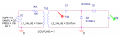
The question is about transform input source (10kHz, 22V AC) to output 1V AC and connect it to voltage doubler.
So what I have done so far is attached. I uploaded this problem before and many of you helped me but I have problems that I cannot understand yet.
1.
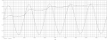
On the first simulation result, the curve looks like sin curve is input voltage of voltage doubler(the one came from transformer) and the other curve is the voltage of vertical capacitor V_out.
Theoretically, the V_out must be increase to the extent of half of the increased input voltage since D2 will be off and D1 is on.
Thus the V_out must be around 400mV approximately but it is about 200mV. I guess it is due to the D1N914 diode but I have no idea how should I analyze this effect. The final value of V_out is approximately 1.6V not 2V(which comes from theory)
2.
As I learend, the V_out must stay constant for some range but what I can observe is decrease of V_out during the period where it must stay constant.(30us~90us for example). It may due to discharging of capacitor but how come it can discharge even there aren't any path for discharging.
3.
The question is about asking the effect of inductance and capacitance on circuit.
What I think is increasing L would make large final convergence of V_out since it leads to higher V_in.
But I have no idea of capacitance.
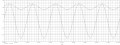
As I increased it, SPICE gives me lower final V_out and relatively curve of V_out becomes more 'flat'.
Why the capacitance change both value and the shape of curve?
'sim2' is the simulation result when both capacitance is changed to 10pF. V_out looks like sine wave.
Even any book/source to find this answer will be appreciated.
The question is about transform input source (10kHz, 22V AC) to output 1V AC and connect it to voltage doubler.
So what I have done so far is attached. I uploaded this problem before and many of you helped me but I have problems that I cannot understand yet.
1.
On the first simulation result, the curve looks like sin curve is input voltage of voltage doubler(the one came from transformer) and the other curve is the voltage of vertical capacitor V_out.
Theoretically, the V_out must be increase to the extent of half of the increased input voltage since D2 will be off and D1 is on.
Thus the V_out must be around 400mV approximately but it is about 200mV. I guess it is due to the D1N914 diode but I have no idea how should I analyze this effect. The final value of V_out is approximately 1.6V not 2V(which comes from theory)
2.
As I learend, the V_out must stay constant for some range but what I can observe is decrease of V_out during the period where it must stay constant.(30us~90us for example). It may due to discharging of capacitor but how come it can discharge even there aren't any path for discharging.
3.
The question is about asking the effect of inductance and capacitance on circuit.
What I think is increasing L would make large final convergence of V_out since it leads to higher V_in.
But I have no idea of capacitance.
As I increased it, SPICE gives me lower final V_out and relatively curve of V_out becomes more 'flat'.
Why the capacitance change both value and the shape of curve?
'sim2' is the simulation result when both capacitance is changed to 10pF. V_out looks like sine wave.
Even any book/source to find this answer will be appreciated.
Attachments
-
 51.2 KB Views: 13
 -
 52.8 KB Views: 17
 -
 12.6 KB Views: 19


