Facebook
 Google
 GitHub
 Linkedin
Hello,
I was trying to create a voltage doubling transformer. Before I finished winding the secondary, I wanted to test it. So I hooked it up in series with a DMM and connected the secondary to another DMM only to discover that it's drawing too much amperage and the secondary has almost no voltage across it.
I'm pretty sure that the inductive reactance of the transformer is too low, but I'm uncertain how to fix that (reducing the wire size seems like an option, but then wouldn't the transformer overheat?). My Radio Shack book's chapter on transformers is rather brief.
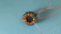
The transformer I'm trying to make should do 9v in, 18v out, and 4a in, 2a out, at 60hz. I'm using a torrid core that measures 20mm OD, 12mm ID, and 10mm high. The core material is suspected to be MnZn. The wire's diameter is 0.67mm stripped and 0.73mm with coating. I'd know more specifically what size it is, but I also got it from Radio Shack as a child and I thew the packaging away eons ago.
As currently wound, the primary measures (at 10mA):
Ideas?
Thanks!
I was trying to create a voltage doubling transformer. Before I finished winding the secondary, I wanted to test it. So I hooked it up in series with a DMM and connected the secondary to another DMM only to discover that it's drawing too much amperage and the secondary has almost no voltage across it.
I'm pretty sure that the inductive reactance of the transformer is too low, but I'm uncertain how to fix that (reducing the wire size seems like an option, but then wouldn't the transformer overheat?). My Radio Shack book's chapter on transformers is rather brief.
The transformer I'm trying to make should do 9v in, 18v out, and 4a in, 2a out, at 60hz. I'm using a torrid core that measures 20mm OD, 12mm ID, and 10mm high. The core material is suspected to be MnZn. The wire's diameter is 0.67mm stripped and 0.73mm with coating. I'd know more specifically what size it is, but I also got it from Radio Shack as a child and I thew the packaging away eons ago.
As currently wound, the primary measures (at 10mA):
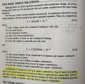
| L | Resistance | Reactance | Z |
| Series 2.177mH | Series 101.4mOhms | 820.71mOhms | 827mOhms |
| Parallel 2.211mH | Parallel 6.757 Ohms | 833.53mOhms | 6.808 Ohms |
Ideas?
Thanks!
Attachments
-
 281.1 KB Views: 16
Last edited: