Transformer gear, does the simulator calculate it wrong ?

Thread Starter

Xenon02

Joined Feb 24, 2021
500
Hello !

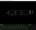
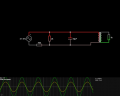
I have a problem with transformer gear in this example :

2022-06-28 (2).jpg
Ratio is 1:1
coupling factor = 0,999 so we can say it's 1,0

So Vd1 = Vd2 but I1 isn't equal I2.
The equations are that Vd1/Vd2 = 0,999 = 1,0 or I2/I1 = 1,0 or N1/N2 = 1,0 but I2 isn't equal I1.

Why ?
 

Thread Starter

Xenon02

Joined Feb 24, 2021
500
How do I calculate Vd1, Vd2, Id1, Id2 in transformer ? I'm asking it because when I change resistor from 1k to 2k or 10k Vd1,Vd2,Id1 and Id2 changes, and I don't know how to calculate them when I don't have any const parameter the only thing I know is that Vd1/Vd2 = Id2/Id1 = N1/N2 = 0,999 or 1,0
 

Ian0

Joined Aug 7, 2020
9,668
The important one for current calculation is L=1H.
The primary will have an impedance of X=2πfL, through which current will flow - the Magnetising current.
This will be in addition to the current that flows because of the load on the secondary.
 

Thread Starter

Xenon02

Joined Feb 24, 2021
500
The important one for current calculation is L=1H.
The primary will have an impedance of X=2πfL, through which current will flow - the Magnetising current.
This will be in addition to the current that flows because of the load on the secondary.
But when I calculate X=2πfL it should have the same current or voltage.
But when I change resistor from 1k to 10k the current changes in both sides, Voltage also changes in both sides.

1656436128484.png


1656436148075.png


I don't know how it works ...
 

Danko

Joined Nov 22, 2017
1,829
In both circuits V1=10Vpeak, frequency F=41.1Hz, coupling K=1:1
Difference is only in windings inductance:

1656436839555.png

1656436886664.png

ADDED:
File "transformer.pdf"
(Transformer is simple on first look,
but is very sophisticated thing,
which is hard for understanding.)
 

Attachments

Last edited:

Thread Starter

Xenon02

Joined Feb 24, 2021
500
You are right here but I2/I1 isn't equal 1,0 or 0,999 in first example it is equal : 5,713/5,715 close to 1 so 0,999
But in second one it is different it should still be 1 or 0,999 because N1/N2. So U1/U2 is equal I2/I1 but 6,0136/23,662 isn't equal 1.
 

Ian0

Joined Aug 7, 2020
9,668
A real transformer is an ideal transformer, with an inductor in parallel with the primary winding.
If it were an ideal transformer (the higher the inductance, the closer to ideal it gets) then the two currents would be equal, but for a real transformer the primary current will be higher by V/(2πfL).
(Even that is a simplification, because there is resistance, core losses etc.)
 

Thread Starter

Xenon02

Joined Feb 24, 2021
500
A real transformer is an ideal transformer, with an inductor in parallel with the primary winding.
If it were an ideal transformer (the higher the inductance, the closer to ideal it gets) then the two currents would be equal, but for a real transformer the primary current will be higher by V/(2πfL).
(Even that is a simplification, because there is resistance, core losses etc.)
Ok but why in the simulation where I have ideal parts the currents aren't equal
 

Thread Starter

Xenon02

Joined Feb 24, 2021
500
You don’t.
An ideal transformer has infinite magnetising inductance, and yours has 1 Henry.
Ooo

I thought that ideal transformer is when the coupling factor is equal 1
So may I ask you how to I calculate with 1H and with 100H ?
Because as I see for 1H the equation U1/U2 doesn't work, as well I2/I1 also doesn't work.
But for 100H U1/U2 and I2/I1 works.
 

Ian0

Joined Aug 7, 2020
9,668
Ooo

I thought that ideal transformer is when the coupling factor is equal 1
So may I ask you how to I calculate with 1H and with 100H ?
Because as I see for 1H the equation U1/U2 doesn't work, as well I2/I1 also doesn't work.
But for 100H U1/U2 and I2/I1 works.
Transformers can be non-ideal in many different ways!
The coupling factor controls the leakage inductance.
The leakage inductance is the fraction of the primary inductance that doesn't couple with the secondary inductance.
The magnetising inductance depends on the type of transformer - toroids have much higher magnetising inductance than E-I laminated transformers, and smaller transformers have more magnetising inductance than larger ones.
From my notes, a 3VA pcb mount transformer has a magnetising inductance of 66H. A 1.6VA toroid is 1500H. A 7kVA dual bobbin transformer was 1.02H
These are 230V primaries - 115V primaries will have a quarter of the inductance.
 

Thread Starter

Xenon02

Joined Feb 24, 2021
500
Transformers can be non-ideal in many different ways!
The coupling factor controls the leakage inductance.
The leakage inductance is the fraction of the primary inductance that doesn't couple with the secondary inductance.
The magnetising inductance depends on the type of transformer - toroids have much higher magnetising inductance than E-I laminated transformers, and smaller transformers have more magnetising inductance than larger ones.
From my notes, a 3VA pcb mount transformer has a magnetising inductance of 66H. A 1.6VA toroid is 1500H. A 7kVA dual bobbin transformer was 1.02H
These are 230V primaries - 115V primaries will have a quarter of the inductance.
I'm sorry to be very annoying but I've read that ideal transformer is when we don't have any lost energy (for example in heat. etc.) That the whole energy is changed into electricity.

So I have here a program

1656442126011.png

And this parameter 1H or 100H is not a magnetic inductance but it is primery coil (It's translated into my language) so it is this first coil on the left.


By the way why the value of the primery inductance can change it drastically. Ideal transformer shouldn't bother about that.
What parameter here defines that this is not ideal ? I've set it to 0,999 close to 1 so we can ignore it.

1656442373851.png

1656442392770.png
In here i don't understand "infinite permability" is this parameter avaible in this program?
 

Ian0

Joined Aug 7, 2020
9,668
Permeability is a characteristic of the material that the core is made out of, and its value is called μ
Permeance is a characteristic of the core of a particular transformer, and is equal to μA/l where l is the magnetic path length (the distance the flux covers to move around the core)
Inductance is equal to permeance multiplied by the square of the number of turns.
So infinite permeability would give infinite inductance, and infinite inductance would result in zero magnetising current, so the primary and secondary currents would be equal.
If you look back at @Danko 's calculations, you will see that when he used a large value of inductance the currents became closer to equal.

Just to complete the set, reluctance is the reciprocal of permeance.
Magnetomotive force is the product of current and number of turns
Flux is Magnetomotive force divided by reluctance.
Flux density is flux divided by cross sectional area.
If flux density gets too big, the core saturates and no longer works as a transformer. Yet another example of non-ideal behaviour!
This happens at a flux density of about 1.8 Tesla for iron cores and 0.3T for ferrite.
 

Thread Starter

Xenon02

Joined Feb 24, 2021
500
Permeability is a characteristic of the material that the core is made out of, and its value is called μ
Permeance is a characteristic of the core of a particular transformer, and is equal to μA/l where l is the magnetic path length (the distance the flux covers to move around the core)
Inductance is equal to permeance multiplied by the square of the number of turns.
So infinite permeability would give infinite inductance, and infinite inductance would result in zero magnetising current, so the primary and secondary currents would be equal.
If you look back at @Danko 's calculations, you will see that when he used a large value of inductance the currents became closer to equal.

Just to complete the set, reluctance is the reciprocal of permeance.
Magnetomotive force is the product of current and number of turns
Flux is Magnetomotive force divided by reluctance.
Flux density is flux divided by cross sectional area.
If flux density gets too big, the core saturates and no longer works as a transformer. Yet another example of non-ideal behaviour!
This happens at a flux density of about 1.8 Tesla for iron cores and 0.3T for ferrite.

ahaaaaaaa, okey I think I get it now.
So the simulation gives me an option to change the value of the coil from 1H to 100H. The ideal tranformer if when primary and secondary coil are infinite.

Okej so that's how it works.
As I can understand when I don't have an ideal transformer (ideal here means that the coil value isn't high enough for example 100H etc. ) then I have to use different equations? What do I mean by that is I can't use U1/U2 = I2/I1 = N1/N2 in 1H coil example ?
 

Ian0

Joined Aug 7, 2020
9,668
ahaaaaaaa, okey I think I get it now.
So the simulation gives me an option to change the value of the coil from 1H to 100H. The ideal tranformer if when primary and secondary coil are infinite.

Okej so that's how it works.
As I can understand when I don't have an ideal transformer (ideal here means that the coil value isn't high enough for example 100H etc. ) then I have to use different equations? What do I mean by that is I can't use U1/U2 = I2/I1 = N1/N2 in 1H coil example ?
You could try just making the inductance ridiculously large (say 10000H). I presume the simulator would cope with it, even though practically it would be impossible to make.
The real transformer with 1H primary looks like an ideal transformer with a 1H inductor connected across the primary.
 

Danko

Joined Nov 22, 2017
1,829
So may I ask you how to I calculate with 1H and with 100H ?
You can not change inductance of primary coil,
because in this clever problem, inductance 1 H and C1 capacitance 15 μF
are resonant circuit (tank), which oscillates on frequency 41.09363≈41.1 Hz.
On diagram below you can see currents in L1, C1, L2.
Note, all currents are in different phases.
So current in L2 exactly equals sum of currents L1 and C1.

1656445793516.png
 
Last edited:

Ian0

Joined Aug 7, 2020
9,668
You can not change inductance of primary coil,
because in this clever problem, inductance 1 H and C1 capacitance 15 μF
are resonance circuit (tank), which oscillates on frequency 41.09363≈41.1 Hz.
On diagram below you can see currents in L1, C1, L2.
Note, all currents are in different phases.
So current in L2 exactly equals sum of currents L1 and C1.

View attachment 270363
Power factor correction for a rather peculiar mains frequency!
It also illustrates how the transformer can be non-ideal, but still lossless.
 

Thread Starter

Xenon02

Joined Feb 24, 2021
500
You could try just making the inductance ridiculously large (say 10000H). I presume the simulator would cope with it, even though practically it would be impossible to make.
The real transformer with 1H primary looks like an ideal transformer with a 1H inductor connected across the primary.
I'm sorry I didn't understand the phrase with 1H coil. So the simulation I've shown where I2/I1 isn't equal 1 is because this transformer doesn't work like ideal transformer but with 100H it works very close like ideal. Am I right ?

You can not change inductance of primary coil,
because in this clever problem, inductance 1 H and C1 capacitance 15 μF
are resonance circuit (tank), which oscillates on frequency 41.09363≈41.1 Hz.
On diagram below you can see currents in L1, C1, L2.
Note, all currents are in different phases.
So current in L2 exactly equals sum of currents L1 and C1.

View attachment 270363
I know it is a resonance frequancy because I had a small problem understanding transformer.
Could you please tell me why the current on L2 is equal current on L1 and C1. Shouldn't be that current L2 is equal L1 times alfa ? Like in typical transformer ?

And check this out :

1656447866563.png

When I change the value of the resistor on the second coil, I will change the phase between Currant and Voltage in power supply.
1656447926614.png

So how is it possible that in this circuit :
1656447981044.png

That whenever I change the resistor on the second coil, it won't change the phase like in the first one example.

1656448026181.png
 

Attachments

Top