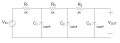
Transfer function of this circuit?

Thread Starter

pww

Joined Feb 5, 2010
7
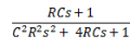
I'm having a hard time analyzing this circuit... I've been told the transfer function that I've obtained is incorrect. I got this as the transfer function:


I did that by finding Vin = [R + C||R] + [C||R] + C

and Vout= C

Please help, I've been told this is wrong but I don't know how to do it otherwise
 

Attachments

Last edited:

The Electrician

Joined Oct 9, 2007
2,986
First, it's obvious that your result is wrong because there are 3 capacitors and your result is only second order. The correct result will have to be third order.

You can solve this problem as a cascade of voltage dividers. R1 and C1 form a loaded voltage divider. You have to add the effect of R2, C2, R3 and C3 loading C1 with their various series/parallel combinations. You start at the output and work your way backwards to figure out the load on C1 and then get the voltage divider ratio of the R1/C1 divider. Once you have that, move one step forward and figure the loaded divider ratio of R2/C2, etc.

You might also do a web search for "ladder networks" and see if you can find any material on solving such networks.

Give it a try and show us your work if you have a problem; then we can help you.
 

Thread Starter

pww

Joined Feb 5, 2010
7
Ok, thanks... I think I got it now

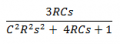
So I set Vout = (C||R) + (C||R) + (C||R)

and then I set Vin = R + (C||R) + (C||R) + C

Then to find the gain I take Vout/Vin and I get this as the transfer function:


Once I plug in all the numbers I got |T(s)| = 0.702747
Is this right?
 

Attachments

Last edited:

The Electrician

Joined Oct 9, 2007
2,986
The transfer function will have to be third order; that means that the denominator will be a cubic. The highest power of s will be 3; you only have s squared.

Imagine that R2, C2, R3 and C3 were gone. Then you would have a simple, unloaded, voltage divider. The transfer function would be:

\(\frac{1/sC1}{1/sC1+R1}=\frac{1}{sR1C1+1}\)

Now imagine R2 and C2 were restored. You would have the series combination of R2 and C2 in parallel with C1. Then the R1/C1 voltage divider would be different because you wouldn't just have C1 as the shunt element in the divider.

Do you understand how voltage dividers work, and how to calculate them?

Have a look at this: http://en.wikipedia.org/wiki/Voltage_divider

Be sure to read the parts about loading effects.
 
Top