 Facebook
 Google
 GitHub
 Linkedin
Please someone kindly assist TS
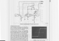
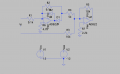
The DUT is a full wave rectifier (2nd image)
Using the XY mode of a scope. I can't get the right output
Also, in image 1, where does the (+) and (-) input go to in the 2nd image
Thank you
The DUT is a full wave rectifier (2nd image)
Using the XY mode of a scope. I can't get the right output
Also, in image 1, where does the (+) and (-) input go to in the 2nd image
Thank you
Attachments
-
 1.4 MB Views: 14
 -
 178 KB Views: 16


