Hi EXPERTS. I need help in understanding this question I am clueless please help. I don't even know where to start. I think it looks like a butterworth filter.
Since we dont really do the homework for you, i'll drop some hints and if you respond we can go little by little to solve this problem, but you'll need to do some of the work as you think about this carefully.
Hint #1:
First, factor the denominator and see if that helps.
Hi Sir. The factor of the transfer function should be H (s) = -1/(s-1) (s+1)
R is the resistor value
i think it's not possible to realize this because it has a negative numerator
Hi Sir. The factor of the transfer function should be H (s) = -1/(s-1) (s+1)
R is the resistor value
i think it's not possible to realize this because it has a negative numerator
We can create an omp amp circuit that inverts. I think I made a irrational assumption my apologies sir. What do we do after we factor the denominator? The book that is prescribed to us is really horrible.
What to do after factoring? Well, i have to see what other circuits you have designed or worked with so far. For example, have you designed or worked with an op amp inverter circuit and/or an op amp voltage follower circuit, or an op amp circuit with some positive gain like 2, 5, 10, etc. ?
Just keep in mind that you are also trying to discover whether or not this can even be done, but you dont want to jump to any conclusions either without at least trying some circuits.
Hi Sir Mr AI.
I was forced to do this subject. Oh well. I have never worked with other omp amp inverter circuits. I really dont know what to do after the factoring the denominator to be honest. I am guessing that i divide the denominator by RC?The book i am using to study is called linear n nonlinear circuits by leon chauo. 1987. I don't understand these concepts. Do you have other material that i can read that will help me. Please help sir.
Thanks.
I like what you've done with the R & C values to create the (s+1) and (s-1) poles. Unfortunately, you only get to use 1 op amp, according to your directions. Ask your professor if that's OK, or if you have to use a single op amp.
By the way, you have not hooked up the op amps correctly. Op amps have 2 inputs, not just one. You have to use both. Remember, feedback always goes to the inverting input, unless you're building a latch, adding hysteresis, or building an oscillator. Look up inverting and non-inverting unity gain configurations. Actually, you don't need to. The negative resistor is going to invert the signal for you. Both op amps would be non-inverting.
If you have to use a single op amp, and not two; I think, because you'll be using negative resistance, you don't need an inverting amplifier, but will use the Sallen-Key architecture. Unfortunately, the Active Filters chapter here on AAC has not been written yet. But there are good resources out there if you Google it. Try Texas Instruments. I know they have a good paper on Sallen-Key filter design.
I may not have solved the problem for you, but I've certainly given you some things to Google, and stuff to read. The negative resistance makes this a little tricky, and cookbook formulas won't work, because negative resistors don't actually exist.
I think you need to redraw your op amp circuits because they dont look right. You cant have the output going right back to the input like that, and inverting stages have to be different than non inverting stages.
Also as the previous post mentions, it looks like you can only use one op amp.
I guess you want to use a negative resistance. That might be the easiest way. The next question seems to imply that is ok to do also. If not, you'd have to try to come up with a scheme that uses positive feedback which can also provide a minus in the denominator, and of course a possible instability.
Here's a transfer function of a slightly different kind that was calculated from a single op amp circuit with an L, C, and using positive feedback, and no negative resistances:
Vout=-Vin*(s^2*C*L+1)/(s^2*C*L-1)
The difference is of course the extra s^2 term in the numerator, but that illustrates the main idea.
I think the heart of the question is, "What is the nature of the polynomial in the denominator of the S-domain transfer function of a low pass filter? How are RLC components connected to achieve this.?"
Could you simply do a passive LC low pass filter followed by an op amp buffer, and satisfy the problem? But is said filter possible at all? My gut feeling is no, even with a negative resistor. How do the RLC values work their way into the transfer function of the filter in various filter configurations? What about an active filter using Rs, Cs, and an op amp? This seems more promising.
Your filter is: H(s) = -1/[ s^2 - 1]
This is a 2nd order filter, because of the s^2. One pole is negative (which is normal) and one pole is positive (which is definitely not normal). And the overall gain is inverting, which MrAl pointed out is trivial to achieve. Actually, the gain is only inverting at high frequency, and becomes positive at low frequency and DC.
The general form of the filter is: H(s) = 1/ [(s/w0)^2 + (s/Qw0) + 1]
This is a general 2nd order low-pass filter equation. Let w0=1 to normalize the filter. Let Q=1/2.
The filter becomes 1/[s^2 + 2s + 1], which has 2 real poles at s = -1
You're a step ahead, because you seem to have a decent idea of how to do it with 2 op amps, even if the pins on your op amps are a little funny. You know that you have 2 real poles, 1 and -1, and the overall gain is inverting. You can make a Sallen-Key style filter have real poles, (Q <= 0.5) and with negative resistance, probably get one of the poles to be positive.
Now how does one use a negative R to change one of the poles to s=+1? Is this even possible? I haven't tried it, and I'm not supposed to do the work for you, since it's your homework. Your question seems to want more of a discussion than an answer to the first part. So maybe I have done some of the work for you.
You know what, i am starting to think that this might be a simpler problem than originally thought. It depends on how we interpret the word used in the question, "realizable". The question that could only be answered by taking the actual course is, "Is an unstable circuit considered realizable?". If we ignore the fact that it is unstable for a minute, then the answer might be "Yes", but if we dont ignore that, then it might be "No", because it saturates and therefore does not work properly.
Someone involved in the actual course would have some idea about what the instructor might be allowing based on previously assigned tasks in that course.
The transfer function \(H(s)=\frac{-1}{s^2-1}\) gives a frequency response
\(H(j\omega)=\frac{1}{1+\omega^2}\)
which is a low pass filter with no phase shift. Now from what I recall this is clearly not realizable with passive components, and I suspect is not realizable with op-amps with real passive components. I don't know how theoretical your course is, but you may have done something on the necessary characteristics of transfer functions for them to be realizable by active filters.
Good observation, Tesla. LP filter with no phase shift. That would be a neat trick.
Of course it's not realizable with passive components. There's no such thing as a negative resistor. Although, I suppose one could use an op amp to spin up a "negative" resistance.
From P2:
(a) The imaginary part of the frequency response of a causal linear system is determined by the Hilbert transform of the real part. In other words, knowledge of the real part is sufficient to completely specify the system, and the imaginary part is "redundant" information.
(b) A check for system causality is to compare the imaginary part of the frequency response with the Hilbert transform of the real part.
Hello All,
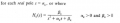
Can we say that for
then for the given circuit that provides a way to realize the transfer function provided that R1 is a negative resistance and it will not be possible for the resistor to be negative.
If we make R1 to be negative it will provide us with the required transfer function.
Is this analysis correct? Since for question 2 we can draw that circuit and make R1 as -1 ohms.
No never. Our lecturer just gives us the book called Linear and non-linear circuits by Leon O. Chuao. he tells us to use the book and answer the questions for tuts after the end of each chapter.
 Facebook
 Google
 GitHub
 Linkedin
 23.1 KB Views: 38