 Facebook
 Google
 GitHub
 Linkedin
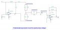
In potentiostat equivalent circuit, working electrode may sink or source the current (AM1) as per bias voltage.
I have attached the potentiostat equivalent circuit for reference.
If working electrode sources the current (during negative bias voltage), then current will flow from working electrode (WE) to trans-impedance amplifier (TIA). At this time, this circuit will work properly and getting TIA output VF1 = - AM1 * R2.
When working electrode sink the current (during positive bias voltage), then current will flow from TIA to WE, and in simulation, VF1 is getting constant 75.51 mV (Actually, it should be VF1 = - AM1 * R2), irrespective of sink current and, whether we vary the bias voltage or not.
Actually it should vary according to sink current and bias voltage but getting fix 75.51 mV.
I have found above problem during simulation, results are attached in file named TIA1 and TIA2.
In TIA1, AM1 is 1u (source) and R2 is 1M so VF1 = 1u * 1M = 1 V. Its working perfect.
In TIA2, AM1 is -1u (sink) and R2 is 1M but VF1 = 75.52 mV which is wrong answer.
Can any suggest for that.
Thank you,
Attachments
-
 61.4 KB Views: 5
 -
 89.4 KB Views: 3
 -
 101.1 KB Views: 4


