Totem Pole for High speed Flash

Thread Starter

Arne1996

Joined Feb 15, 2017
21
Hi everyone,
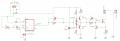
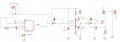
I have a monostable multivibrator which produces a 100ns pulse for my high speed flash. I want to use a totem pole circuit (like an AB-amplifier --> push pull) to switch my LEDs. You can see in the attachement my whole schedule and the totem pole circuit. My totem pole is based on the next site http://www.ecircuitcenter.com/Circuits/pushpull/pushpull.htm (chapter “diode bias”)
What do you think about the schedual? I'm wondering if the diode (D1 & D2) and the resistor (R9 & R7) are necessary...

Kind regards

Totem Pole for High speed Flash_upload_2017-3-29_16-7-47.gif
 

Attachments

Alec_t

Joined Sep 17, 2013
14,280
I don't see any obvious reason to have D1,D2,R7,R9, unless you want to produce an extremely rapid sequence of pulses (in which case those components might help to speed up the switch from push to pull and vice versa). What are the R7/9 values?
BTW the IRF540 is unsuitable as it isn't a logic-level type so won't be switched on fully by the ~4.3V pulse on its gate.
 

Alec_t

Joined Sep 17, 2013
14,280
Simulation shows that D1,D2,R7,R9 don't affect the rate of change of drive voltage but do increase the voltage swing available from the push-pull driver.
PushPullComparison.GIF
 
Last edited by a moderator:

RichardO

Joined May 4, 2013
2,270
For an application like this where very high speed is needed I would recommend against doing your own FET driver. For example a TC4426 only costs a couple of bucks. A search for MOSFET drivers will find a huge number of them are available.
 

Thread Starter

Arne1996

Joined Feb 15, 2017
21
For an application like this where very high speed is needed I would recommend against doing your own FET driver. For example a TC4426 only costs a couple of bucks. A search for MOSFET drivers will find a huge number of them are available.
Isn't the TC4427 better in my case? the TC4426 gives an inverted output and the TC4427 a non-inverting output..
 

RichardO

Joined May 4, 2013
2,270
Isn't the TC4427 better in my case? the TC4426 gives an inverted output and the TC4427 a non-inverting output..
As a habit, I usually use the inverting part. It does look like the non-inverting part may work better in your case.

You should check the speed and propagation delay of the inverting versus the non-inverting part. You may find that using the Q-bar output of the one-shot and the inverting part is a bit faster...
 

Thread Starter

Arne1996

Joined Feb 15, 2017
21
As a habit, I usually use the inverting part. It does look like the non-inverting part may work better in your case.

You should check the speed and propagation delay of the inverting versus the non-inverting part. You may find that using the Q-bar output of the one-shot and the inverting part is a bit faster...
Thanks everyone for the tips/help! I did some adjustments at the schedual (new monostable multivibrator & TC4427).
The new monostable multivibrator has the least signal delay if you sort on Mouser all the multivibrators on signal delay.
upload_2017-4-4_10-42-36.png
 

RichardO

Joined May 4, 2013
2,270
Don't forget to ground pin 4 of the TC4427. If you don't _bad_ things will happen.

Also, I don't think there is anything to gain by adding the 2.7K resistor and variable cap to the input of the TC4427. n fact, I would expect a slight degradation in switching delay.
 

Thread Starter

Arne1996

Joined Feb 15, 2017
21
Don't forget to ground pin 4 of the TC4427. If you don't _bad_ things will happen.

Also, I don't think there is anything to gain by adding the 2.7K resistor and variable cap to the input of the TC4427. n fact, I would expect a slight degradation in switching delay.
oh okey, but I can experiment with that I think :) and yes, I will ground every pin which isn't connected to anything!
Just one question, I have a 3.3R resistor (R1), so there will be a current of 1.5A. The absolute maximum of the TC4427 is 1.5A, isn't this too dangerous/healthy for the IC?
Thanks in advance!
 

RichardO

Joined May 4, 2013
2,270
oh okey, but I can experiment with that I think :) and yes, I will ground every pin which isn't connected to anything!
No!!! Only ground unused inputs.

Just one question, I have a 3.3R resistor (R1), so there will be a current of 1.5A. The absolute maximum of the TC4427 is 1.5A, isn't this too dangerous/healthy for the IC?
I missed seeing the 3.3 ohm resistor. It should not be there. Pin 6 (Vdd) of the TC4427 should connect directly to a power supply of at least 10 volts and not more than 18 volts. This higher voltage is needed because you are not using a "logic" power FET.

I just noticed that you do not show any power supply bypassing. There must be a 0.1uFf ceramic capacitor right between pins 4 and 8 of of the 74'123 and between pins 3 and 6 of the TC4427. The leads of these capacitors must be very short -- less than 1/2" total for each cap. The TC4427 also needs a bulk bypass cap near its power supply pins. Use something like a 10uF electrolytic.

The LED also needs heavy duty power supply bypassing. Near the connector pins you should put a 0.1uF ceramic. Then parallel this with another 10uF electrolytic. Finally you probably need a few hundred to a few thousand uF of capacitance in parallel with that. Don't forget that you need a very heavy ground from the power supply to the LED driver circuit.
 

Thread Starter

Arne1996

Joined Feb 15, 2017
21
No!!! Only ground unused inputs.


I missed seeing the 3.3 ohm resistor. It should not be there. Pin 6 (Vdd) of the TC4427 should connect directly to a power supply of at least 10 volts and not more than 18 volts. This higher voltage is needed because you are not using a "logic" power FET.

I just noticed that you do not show any power supply bypassing. There must be a 0.1uFf ceramic capacitor right between pins 4 and 8 of of the 74'123 and between pins 3 and 6 of the TC4427. The leads of these capacitors must be very short -- less than 1/2" total for each cap. The TC4427 also needs a bulk bypass cap near its power supply pins. Use something like a 10uF electrolytic.

The LED also needs heavy duty power supply bypassing. Near the connector pins you should put a 0.1uF ceramic. Then parallel this with another 10uF electrolytic. Finally you probably need a few hundred to a few thousand uF of capacitance in parallel with that. Don't forget that you need a very heavy ground from the power supply to the LED driver circuit.
Thank you for the help, I was just looking into the datasheets and there was also a lot of information about bulk bypass capacitors! The 4.7Ohm resistor also doesn't has to be there if I'm not wrong?
My schematic now looks like this now (capacitors have now long leads but on my PCB-design I will shorten them like you said)
upload_2017-4-7_14-27-49.png
thank you again!
 

RichardO

Joined May 4, 2013
2,270
Thank you for the help, I was just looking into the datasheets and there was also a lot of information about bulk bypass capacitors! The 4.7Ohm resistor also doesn't has to be there if I'm not wrong?
My schematic now looks like this now (capacitors have now long leads but on my PCB-design I will shorten them like you said)
View attachment 124201
thank you again!
R10 must be there. It is used to limit the current into the current sense transistor (2N6488). I would a value more like 50 ohms for R10 and use a value of about 1000pf to 0.01uf for C6 (the cap in parallel with it). You must _not_ have a cap to ground on the output of the TC4427.

The 2N6488 may not work very well in this circit since it is a relatively slow device considering the pulse width you are using. I think a better choice would be a 2N4401, 2N2219 or similar high speed switching transistor.
 

Thread Starter

Arne1996

Joined Feb 15, 2017
21
R10 must be there. It is used to limit the current into the current sense transistor (2N6488). I would a value more like 50 ohms for R10 and use a value of about 1000pf to 0.01uf for C6 (the cap in parallel with it). You must _not_ have a cap to ground on the output of the TC4427.

The 2N6488 may not work very well in this circit since it is a relatively slow device considering the pulse width you are using. I think a better choice would be a 2N4401, 2N2219 or similar high speed switching transistor.
Today I got the components and I tested the TC4427! I took as a resistor R10 8.2R because otherwise there is too much delay and I still got less then 1.5A.
One thing is I don't get, first you say the value of C6 is better about 1000pf to 0.01uf and after that sentence you say C6 doesn't needs to be there... I placed that capacitor because in the datasheet I saw the figure below.
upload_2017-4-10_16-3-3.png
Thanks for all the help, I progressed a lot!
 

bertus

Joined Apr 5, 2008
22,270
Hello,

The capacitor on the output of the TC4427 is only there for testing the switching speed.
In normal use the capacity of the fet to be driven will be seen by the TC4427 and the external capacitor can be left out of the circuit.

Bertus
 

Thread Starter

Arne1996

Joined Feb 15, 2017
21
hi everyone
its a while ago. I did some research and ordered the schematic above into a PCB. I soldered everything but now I have some trouble with my totem pole.
Just to say, I first tested the circuit with through whole components on a breadboard and it worked perfectly. Now with SMD components it doesnt work anymore. I measured every lane of the pcb if everything is connected with the right component/pin.
Same set up, so I turn on and I get the 5V signal on the output of the TC4427 which is also at input A. But the VDD is 12V so it must be 12V output voltage and not 5V? does anyone now how I can find the mistake in this one? already soldered a new IC TC4427 because I thought the first one wasn't good soldered but it is something else... didnt used the output of the multivibrator (instead just 5V) and also after the IRF540 I didnt connect anything because I first wanted to know if the TC4427 worked... Normally that cant effect the working of the IC TC4427 I think...
Please some help?
thanks in advance!
upload_2017-5-5_14-4-24.png
upload_2017-5-5_14-18-22.png
 

Alec_t

Joined Sep 17, 2013
14,280
I have a job to see the detail in the pcb, but U2 pin6 seems to be grounded? Pin 8, which should be NC, is also grounded.
 
Top