 Facebook
 Google
 GitHub
 Linkedin
HI!
I am a college student majoring in electricity and electronics in Korea
I'm currently working on a pfc converter and I have a question for engineers
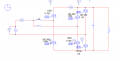
Photo 1 is a topology trying to make 60vdc with 20ac
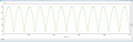
The second picture is an output voltage waveform for it, shouldn't it look like a dc instead of a radio circuit like that?
And I know that 2 boost converters operate with 180 degree phase difference but I don't know how to do the switch duty ratio
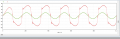
The third photo shows the duty ratio of the switch operating at 100 kHz from 0 to 200 using the gating block
Nevertheless, the input voltage current waveform changes, but the output voltage does not change
I wonder how the duty ratio should be to increase the output voltage
I am a college student majoring in electricity and electronics in Korea
I'm currently working on a pfc converter and I have a question for engineers
Photo 1 is a topology trying to make 60vdc with 20ac
The second picture is an output voltage waveform for it, shouldn't it look like a dc instead of a radio circuit like that?
And I know that 2 boost converters operate with 180 degree phase difference but I don't know how to do the switch duty ratio
The third photo shows the duty ratio of the switch operating at 100 kHz from 0 to 200 using the gating block
Nevertheless, the input voltage current waveform changes, but the output voltage does not change
I wonder how the duty ratio should be to increase the output voltage
Attachments
-
 13.2 KB Views: 28
 -
 14.6 KB Views: 28
 -
 16.5 KB Views: 25


