total power from the source and power factor

RBR1317

Joined Nov 13, 2010
715
For sin(0.9270), you get a positive number! The full calculation is here. Thanks.
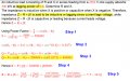
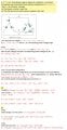
Looking at the phasor diagram for a load resistance in series with a reactance, one can see that it is the sin() of the phase angle that determines whether the reactance is positive or negative. So how does one know if the phase angle is positive or negative? That is decided when the given power factor is either lagging or leading.
SourcePhaseImpedance.png

So in your calculation, where does the power factor determine if the reactance of the load is positive or negative?
 

Thread Starter

PG1995

Joined Apr 15, 2011
832
Thank you, @MrAl, @RBR1317.

So in your calculation, where does the power factor determine if the reactance of the load is positive or negative?
In step 2, if it was given in the problem statement that the power factor is leading then I'd have made phase angle 0.9273 negative instead of positive. Step 2 is the crucial one. In case of a negative phase angle, i.e. -0.9273, Q would also come to be negative.

It might be that the formula used in step 5 is not a right way to proceed to find the impedance. Thank you.


Attachments

RBR1317

Joined Nov 13, 2010
715
So I don't understand how the indicated change in sign happened. And don't tell me that the quantity "X" is anything but a simple magnitude.
SourcePhaseImp.png
 

MrAl

Joined Jun 17, 2014
13,709
Thank you, @MrAl, @RBR1317.


In step 2, if it was given in the problem statement that the power factor is leading then I'd have made phase angle 0.9273 negative instead of positive. Step 2 is the crucial one. In case of a negative phase angle, i.e. -0.9273, Q would also come to be negative.

It might be that the formula used in step 5 is not a right way to proceed to find the impedance. Thank you.

Hi again,

That's what i was telling you several posts back and you did not seem to pick up on it back then. What it turns into is a matter of convention, but we also have the context to consider which seems well defined and that is that this problem seems to reside in the realm of power line applications such as 120vac 60Hz in the US or 230vac 50 Hz in the UK. That, and the fact that we dont think we have to design very complicated networks for the simpler problems.

Just to restate the complex form of the problem...
If we start with a complex impedance Z then we have:
VAcomplex=E^2/Z
and if we then want to find Z we can do:
Z=E^2/VAcomplex
and this should work whether we have the impedance Z=a+b*j or Z=a-b*j.
 

Thread Starter

PG1995

Joined Apr 15, 2011
832
Thank you.

So, the best way to find Z = R ± jX is the following and then choosing the sign depending upon the power factor.

R=Vrms²/P ; X=Vrms²/Q
 

MrAl

Joined Jun 17, 2014
13,709
Thank you.

So, the best way to find Z = R ± jX is the following and then choosing the sign depending upon the power factor.

R=Vrms²/P ; X=Vrms²/Q
Hi,

Yes that is reasonable considering the kind of application.
Actually i think the terms "leading" and "lagging" may be more or less confined to power line applications because in an application that required a phase reference of a specific value that could even be multiples of 360 degrees would probably always be specified as just the angle itself without requiring the somewhat vague lead or lag qualifier. The only other possibility for non power line applications is when the application normally only sees a small angle and then the terms lead and lag may make sense then too.
 

Thread Starter

PG1995

Joined Apr 15, 2011
832
Hi

Please have a look here, or check this link for higher resolution.The answer to part (b) is incorrect. It should be 864 kW, 648 kvar. Anyway, the answer to part (a) is correct. Seemingly, it looks like I didn't make any mistake. Could you please help me to trace out the error in part (b)? Thank you.
 

Attachments

MrAl

Joined Jun 17, 2014
13,709
Hi

Please have a look here, or check this link for higher resolution.The answer to part (b) is incorrect. It should be 864 kW, 648 kvar. Anyway, the answer to part (a) is correct. Seemingly, it looks like I didn't make any mistake. Could you please help me to trace out the error in part (b)? Thank you.
Hi,

So that 4157v is the line to line RMS voltage?
And the reference phase is Vab and not just Va?

One thing seems clear right away if that is all true and that is that you already know the voltage across one phase, and an ideal voltage source voltage is invariant with load.
 
Top