Facebook
 Google
 GitHub
 Linkedin
Thank you.
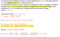
I did find Z_load to be 29.2967+j39.0626 and |I| also found to be 25.6002 A. I believe that the calculations were correct.The supply voltage is equal to the sum of the line drop and the load drop, Vs=|I|⋅(Z_line+Z_load).
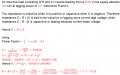
I already did.The current magnitude |I| is found from the given load voltage (1250 V-rms) and consumption (32 kVA).
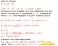
I already found Z_load but don't know how to separate the current I into its real and imaginary parts. I don't know how to proceed. The same goes for V. Only the magnitudes of voltage and current, Vrms and Irms, are known. Thanks for your help.The line impedance is given, (9+j13).
The load impedance is calculated Z_load=1250/I, however the current |I| must be separated into its real and imaginary parts using the given power factor at the load.