 Facebook
 Google
 GitHub
 Linkedin
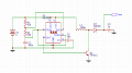
I've followed some schematics for creating a boost converter using a 555 timer. I would like to boost a 3.7v 18650 cell to 12 volts. My circuit seems to work but my output is over 70 volts. I've tried to change out some of the components, different values for the resistors or larger/smaller inductor, but I only get a difference of 1 or 2 volts. The only thing that changes the output significantly is the timing capacitor on the 555 timer circuit, but I have to put a rather large capacitor here to make much of a difference. I've tried using an online calculator for the 555 timer as well as for a boost converter circuit since my own understanding and calculations are probably off.
https://learn.adafruit.com/diy-boost-calc/the-calculator
http://www.ohmslawcalculator.com/555-astable-calculator
How can I adjust my circuit to get 12 volts out?
https://learn.adafruit.com/diy-boost-calc/the-calculator
http://www.ohmslawcalculator.com/555-astable-calculator
How can I adjust my circuit to get 12 volts out?
Attachments
-
 22.1 KB Views: 30

")


