to use a resistor for an IC's input or to not.

BobaMosfet

Joined Jul 1, 2009
2,211
Don't know how what I posted got changed to mA, it is actually uA. Here is a screen clip from the datasheet:

View attachment 240918

Notice the range of input voltages over which this applies. It applies whenever the voltage on the input pin is between the power supply rails to the chip.

Now look at the spec you are quoting:

View attachment 240920

Notice that it applies ONLY when the voltage is less than 0 or higher than the supply voltage.

Input leakage current, though a strange way of saying it, is the spec used to determine how much current an input might source or sink.

My statements about not needing a resistor are qualified by the voltage staying in range.

You are also misinterpreting the absolute max specification. 20 mA is not the maximum current the pin might draw at any input voltage. If you put 100V on the pin, it will, albeit briefly, draw more than 20 mA. 20 mA is the maximum current you can allow to flow into a pin with damaging it.

Reading datasheets is a skill you have to acquire. They are not obvious.

Bob

@BobTPH- No, you're misreading the datasheet. You prove my point. Look at the range over which the voltage applies for leakage current:

1623417995688.png

FOR D060, it is saying Vss (which is ground) is less than or equal to Vpin, which is less than or equal to Vdd (Positive) AT HIGH IMPEDANCE. Which means it's tri-stated. Leakage current is the parasitic current. I don't know how to make it any plainer for you. And I checked it with MicroChip to confirm my understanding.

The input clamp spec that I'm quoting shows the pins have protection diodes and anything above or below those amounts gets dumped to a rail- My point is that they are saying that individual pins can handle up to +/-20mA and will unless current is limited (source or sink).
 

Ian0

Joined Aug 7, 2020
13,279
An input pin has (usually) a 2 transistor input stage, often with over and undervoltage protection All these elements will have some leakage from the power rail (when the input is low) and from the negative rail (when the input is high). That is where the leakage current comes from. That is a seperate issue from drive current for inputs and outputs.
Actually, it’s exactly the same issue. The current required to drive the input is the same as the leakage current, because it has to overcome the leakage current in order to drive the pin.
 

Ian0

Joined Aug 7, 2020
13,279
@Ian0 - Um.... It doesn't work that way. Current is never 'forced' through something. It is attracted through it by the force of voltage- and whatever current is aloud to flow through that path will flow through it unless something prevents it.
Current is forced into the input pin (protection diodes) by driving it to a higher voltage than Vcc or a lower voltage than Vss.
 

BobTPH

Joined Jun 5, 2013
11,654
@BobTPH- No, you're misreading the datasheet. You prove my point. Look at the range over which the voltage applies for leakage current:

View attachment 240965

FOR D060, it is saying Vss (which is ground) is less than or equal to Vpin, which is less than or equal to Vdd (Positive) AT HIGH IMPEDANCE. Which means it's tri-stated. Leakage current is the parasitic current. I don't know how to make it any plainer for you. And I checked it with MicroChip to confirm my understanding.

The input clamp spec that I'm quoting shows the pins have protection diodes and anything above or below those amounts gets dumped to a rail- My point is that they are saying that individual pins can handle up to +/-20mA and will unless current is limited (source or sink).
"At high impedance", in this context means the pin is configured as an input rather than an an output. Tri-state only has meaning for outputs. Do you do much work with microcontrollers?

Edit:

5.0 I/O PORT As with any other register, the I/O register(s) can be written and read under program control. However, read instructions (e.g., MOVF GPIO, W) always read the I/O pins independent of the pin’s Input/Output modes. On Reset, all I/O ports are defined as input (inputs are at high-impedance) since the I/O control registers are all set.
Bolding is mine.

Bob
 

BobaMosfet

Joined Jul 1, 2009
2,211
Actually, it’s exactly the same issue. The current required to drive the input is the same as the leakage current, because it has to overcome the leakage current in order to drive the pin.
Well, that would mean that your input current is obviously greater than the leakage current, or it couldn't overcome it....
 
Last edited:

BobaMosfet

Joined Jul 1, 2009
2,211
"At high impedance", in this context means the pin is configured as an input rather than an an output. Tri-state only has meaning for outputs. Do you do much work with microcontrollers?

Edit:


Bolding is mine.

Bob
No need to get smart. At this point, while I see what you're saying, you're not arguing with me, you're arguing with MicroChip. I must know the correct answer so at this point, I'm going back to them and get a better explanation.

MEANWHILE- If anyone has one of these PIC micrcontrollers and wants to put a 1-Ohm resistor between a 5V supply and an input pin, then check the drop across the resistor with a DMM, that will answer the question imperically as to how much current is being drawn. I would, but I don't have one of these MCUs.
 
Last edited:

BobaMosfet

Joined Jul 1, 2009
2,211
Precisely. That's what the input current does - it overcomes the leakage current.
@BobTPH, @Ian0
Okay, so here's the deal. Read slowly, there is a lot for you to digest.

Leakage current is a residual parasitic leak from the transistors that control the direction of the pin. And it's path is through the transistors to ground, NOT through the input pin. All the leakage current does is impact the transistor logic state on the pin IF it is configured in a high-impedance state which in ALL CASES means floating/tri-state/high-impedance. Unless the input pin is pulled in a direction from an external source (or internal pull-up, pull-down), it is floating/high-z/tri-stated when in input mode. PERIOD.

The leakage current value in the spec sheet has NOTHING to do with limiting current on the input pin. Only protection circuitry (if available) which dumps excess to the rails will limit current- and even that has a limit to what it can handle.

I agree with you BobTPH- it's important to know how to read a datasheet. I'm glad I know how to.
 

Ian0

Joined Aug 7, 2020
13,279
Stop, you don't even know what you're talking about.
Maybe it's not me that doesn't know what he is talking about.

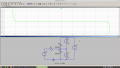
So, here's a model of the input pin, with its protection diodes, and two current sources to represent the leakage. One is 2uA and the other 1uA to give a net leakage out of the pin of 1uA.
The input voltage (V2) is swept from -1V to +6V, and the graph shows the input current.
Screenshot at 2021-06-11 17-19-54.png
As you can see whilst the input voltage is between Vss and Vdd, the input current is just sufficient to overcome the leakage current. When the input voltage exceeds the Vdd-Vss range, current is forced through the protection diodes and quickly goes off scale, and will easily exceed the 20mA maxiumum if not limited by a resistance.
 
Last edited:

BobTPH

Joined Jun 5, 2013
11,654
I give up. I will never convicen
@BobTPH, @Ian0
Okay, so here's the deal. Read slowly, there is a lot for you to digest.

Leakage current is a residual parasitic leak from the transistors that control the direction of the pin. And it's path is through the transistors to ground, NOT through the input pin. All the leakage current does is impact the transistor logic state on the pin IF it is configured in a high-impedance state which in ALL CASES means floating/tri-state/high-impedance. Unless the input pin is pulled in a direction from an external source (or internal pull-up, pull-down), it is floating/high-z/tri-stated when in input mode. PERIOD.

The leakage current value in the spec sheet has NOTHING to do with limiting current on the input pin. Only protection circuitry (if available) which dumps excess to the rails will limit current- and even that has a limit to what it can handle.

I agree with you BobTPH- it's important to know how to read a datasheet. I'm glad I know how to.
If this is an answer from Micrichip, what, precisely, did you ask them? Because the answer, as far as I can tell, has nothing to do with what we disagree on.

Based on your understanding, what current will my multimeter read if I connect it between Vdd and a pin configured as input? Same for ground. I contend it will read less than 1uA. If you can’t give the exact value, give a lower limit. Then I will do the experiment.

Here is my assertion, which has not changed throughout this discussion: You do not need a resistor to limit the current to input pin as long the voltage is between Vss and Vdd.

Bob
 

BobaMosfet

Joined Jul 1, 2009
2,211
@BobTPH, @Ian0 I warned you, I was stubborn. I have been looking all over the internet for information regarding leakage currents, and so forth as well. I realize why I'm stubborn this way. I keep pushing back at you because (I just realized this), I'm trying to get you to give me a different answer from another perspective, because how you're saying it isn't clicking, and what I'm saying makes sense...

I found another thread where @bertus provided additional specific information on this issue from TI, and their explanation made sense.... and once it did, I feel foolish, because at the end of the day, High Impedance means just that (and I know that- which makes me feel even more silly)-- High impedance limits current.

My apologies- and thank you for your patience.

I think the takeaway for anyone is this- read your datasheet carefully, understand it (me included), because whether or not your IC can protect itself is something that can vary depending on IC.
 

BobaMosfet

Joined Jul 1, 2009
2,211
Maybe it's not me that doesn't know what he is talking about.

So, here's a model of the input pin, with its protection diodes, and two current sources to represent the leakage. One is 2uA and the other 1uA to give a net leakage out of the pin of 1uA.
The input voltage (V2) is swept from -1V to +6V, and the graph shows the input current.
View attachment 240979
As you can see whilst the input voltage is between Vss and Vdd, the input current is just sufficient to overcome the leakage current. When the input voltage exceeds the Vdd-Vss range, current is forced through the protection diodes and quickly goes off scale, and will easily exceed the 20mA maxiumum if not limited by a resistance.
Yeah, brilliant, makes sense now. Sometimes I have to read slowly myself.... :p
 
Top