TMP36 reading inaccurate values on arduino

Status
Not open for further replies.

Reloadron

Joined Jan 15, 2015
7,892
Thanks but i used this one too . it does not work . the problem is in the reading values as you can see from the results . Voltage changes every second and it causes a huge change of temp
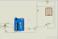
Then something else is wrong. I ran the code sample I posted on an Arduino Uno and using a DC reference source I get stable readings and accurate readings based on mV applied. You may want to take a good look at your wiring and sensor because you should have stable readings. Remove the TMP36 entirely and short A0 to common GND You should see a stable reading. If that is the case I would start checking connections and the pin-out on the sensor.

Also, per the above I would just disconnect the D/O line so all you have is the very basics. Once you get stable temperatures and good readings then I would move along to the heater driver circuit which could use improvement. Starting with a Logioc Level MOSFET regardless of the low turn on voltage spec for the IRF520.

Ron
 
Last edited:

MisterBill2

Joined Jan 23, 2018
27,639
I see now that a resistor has appeared in the collector lead of the driver transistor. Was that just a drawing problem, or was there really no resistor in that line??
 

crutschow

Joined Mar 14, 2008
38,538
Is the heater operating?
Does the ground for the heater MOSFET go directly to the power supply ground to avoid its current causing ground bounce and affecting the temperature reading?
 

SamR

Joined Mar 19, 2019
5,494
Where did the TMP36 come from, IE is it chineseium? Have you tried replacing it? Do you have a known good temp sensor? From what I have seen so far, it points to the TMP36 as being the problem. Have you tried an LM35? My memory fails me but I had the same problem with either the TMP36 or LM35. One worked perfectly and the other had the same inconsistency. Good Luck!
 

Thread Starter

Kadav

Joined May 11, 2018
158
Is the heater operating?
Does the ground for the heater MOSFET go directly to the power supply ground to avoid its current causing ground bounce and affecting the temperature reading?
Hello i have come to find out that without anything connected to the sensor . the temperature does not bounce . so how do i remove the ground noise . i think it's the common ground that is causing bounce backs . hence it can not read the right values ..

some one suggested to increase the capacitance at the ground .. what do you think about it .
 

MisterBill2

Joined Jan 23, 2018
27,639
The way to avoid ground line noise is to arrange the connections so that no other current flows in the signal loop ground return wires. Usually that means that the sensor connections only include one point of being connected to the signal common.
In industry we always went with a separate pair of conductors from the sensor to the analog input, and I never called the other wire "ground", it was always "signal return", not part of the system common except tied to common at one point. Thus there were never ground loops.
A ground loop is a portion of a signal loop that has other currents flowing through it. That is the actual definition, once it becomes clear to you it is a lot simpler to avoid them.
 

Thread Starter

Kadav

Joined May 11, 2018
158
The way to avoid ground line noise is to arrange the connections so that no other current flows in the signal loop ground return wires. Usually that means that the sensor connections only include one point of being connected to the signal common.
In industry we always went with a separate pair of conductors from the sensor to the analog input, and I never called the other wire "ground", it was always "signal return", not part of the system common except tied to common at one point. Thus there were never ground loops.
A ground loop is a portion of a signal loop that has other currents flowing through it. That is the actual definition, once it becomes clear to you it is a lot simpler to avoid them.
sorry i did not understand what you said

Do you mean that we should basically create a different Ground from the system with the arduino or what ?
 

Thread Starter

Kadav

Joined May 11, 2018
158
1594114792282.png


I have seen that when i use a TMP36 sensor alone without the other components the results are steady from a research i have seen that if i add a de coupling capacitor it will remove the ground noise but what if i added a diode on It can't it produce a result sinc the diode will block the ground back signal ?
 

Thread Starter

Kadav

Joined May 11, 2018
158
sorry i did not understand what you said

Do you mean that we should basically create a different Ground from the system with the arduino or what ?
I only have one arduino so i don't see exactly how i can do it ...
 

Deleted member 115935

Joined Dec 31, 1969
0
Do not put a diode in the ground line.

The signal earth from the TMP36, is it wired directly back to the arduino ?
Where is the heater ground return being wired back to ?

The picture you show, the high ground current from the heater is sharing a wire with the senser ground. Good old V=IR, the resistance of the cable would mean the ground at the senser would bounce every time the heater current changed.

A possible answer, is in the software, is to stop driving the heater whilst your taking the measurement ? Then the ground current would be constant. As the heater is going to have a large thermal lag, the short time of the measurement will be insignificant.

As mentioned by others, personally, I'd wire the ground wire from the heater back direct to the power supply only.
And the Arduino ground direct back via another wire to the power supply.
 

Thread Starter

Kadav

Joined May 11, 2018
158
Do not put a diode in the ground line.
The signal earth from the TMP36, is it wired directly back to the arduino ?
Where is the heater ground return being wired back to ?

The picture you show, the high ground current from the heater is sharing a wire with the senser ground. Good old V=IR, the resistance of the cable would mean the ground at the senser would bounce every time the heater current changed.

A possible answer, is in the software, is to stop driving the heater whilst your taking the measurement ? Then the ground current would be constant. As the heater is going to have a large thermal lag, the short time of the measurement will be insignificant.

As mentioned by others, personally, I'd wire the ground wire from the heater back direct to the power supply only.
And the Arduino ground direct back via another wire to the power supply.

The signal earth from the TMP36, is it wired directly back to the arduino ?
Where is the heater ground return being wired back to ?
all the connections grounds are connected with the arduino ground

A possible answer, is in the software, is to stop driving the heater whilst your taking the measurement ? Then the ground current would be constant. As the heater is going to have a large thermal lag, the short time of the measurement will be insignificant.
I need to heat so that i can measure the temperature . because i am using a PID temperature system

As mentioned by others, personally, I'd wire the ground wire from the heater back direct to the power supply only.
And the Arduino ground direct back via another wire to the power supply.
What would be the use of the MOSFET in that case and the arduino if the the heater is just connected to the Power supply ?

Can you make me a pencil drawing if you can i don't understand the concept

thanks
 

MisterBill2

Joined Jan 23, 2018
27,639
Andrewmm provided the exact explanation in post #30.
Now I am asking, "Does the arduino provide a terminal that is intended to be the common return terminal for those analog inputs? If not, then it is poorly designed.
 

dendad

Joined Feb 20, 2016
4,641
There are a number of gnd pins on the Arduino.
Use one for the temp sensor and only the temp sensor!
Then there will only be the sensor current in that lead. Use another gnd pin for the output switching return.
Are you powering the Arduino from the USB or a power supply?
It is not a good idea to use the USB for power when reading the analog inputs if the code is set to have the 5V as the ref volts as the USB power can fluctuate quite a bit. I did not look at your code to see if you are using the 5V or the internal Vref, but an just assuming you have left it to the default 5V.
Maybe I'd best go and look at the code ;)
EDIT. It looks like you are.
Try selecting the internal Vref, but you will have to alter the calculation to suit.

Also, another trick is to read a couple of times and only use the reading if both are tha sam, or close.
And it may be worth averaging a number of readings over the time that is a full mains cycle in your location. That will remove the mains hum.
 
Last edited:

MisterBill2

Joined Jan 23, 2018
27,639
OK, now we have the answer about power return connections. One of them should be the preferred one to use with the analog input channels.
And I am pleased to see that some others are using the term "code" to reference the program listings. Why they call it a "sketch" when it is not a sketch is not very clear.
 

Deleted member 115935

Joined Dec 31, 1969
0
all the connections grounds are connected with the arduino ground


I need to heat so that i can measure the temperature . because i am using a PID temperature system

What would be the use of the MOSFET in that case and the arduino if the the heater is just connected to the Power supply ?

Can you make me a pencil drawing if you can i don't understand the concept

thanks


Do not connect all the grounds at the Arduino.
connect the Arduino ground and the heater ground back at the power supply


Re PID. PID is how you decide what PWM to drive the Heater with.
There is nothing to say you can not stop driving the heater for the few mili seconds you are taking the measurement.
 

Thread Starter

Kadav

Joined May 11, 2018
158
There are a number of gnd pins on the Arduino.
Use one for the temp sensor and only the temp sensor!
Then there will only be the sensor current in that lead. Use another gnd pin for the output switching return.
Are you powering the Arduino from the USB or a power supply?
It is not a good idea to use the USB for power when reading the analog inputs if the code is set to have the 5V as the ref volts as the USB power can fluctuate quite a bit. I did not look at your code to see if you are using the 5V or the internal Vref, but an just assuming you have left it to the default 5V.
Maybe I'd best go and look at the code ;)
EDIT. It looks like you are.
Try selecting the internal Vref, but you will have to alter the calculation to suit.

Also, another trick is to read a couple of times and only use the reading if both are tha sam, or close.
And it may be worth averaging a number of readings over the time that is a full mains cycle in your location. That will remove the mains hum.
What do youmeanby internal VREF. is it AREF?
 

Reloadron

Joined Jan 15, 2015
7,892
All of your grounds should be common bonded. If the problem persist you can try placing a 100nF cap between your input pin A0 and Gnd. Most of what you describe sounds like a loose connection point. Using your code and an ARduino Uno I get stable accurate readings and I am not using a cap input to ground.

Ron.
 

Thread Starter

Kadav

Joined May 11, 2018
158
I see now that a resistor has appeared in the collector lead of the driver transistor. Was that just a drawing problem, or was there really no resistor in that line??
NO the resistor was therebut i had forgotten to put it in simulation
 

Thread Starter

Kadav

Joined May 11, 2018
158
1594135717794.png

Is this setting more accurate to produce a better result than the one where i connect the heater ground to the arduino(image below)
in order to avoid ground noise
and should i connect a flyback diode in the process , of which i don't understand the need ?
View attachment 211484
 

Attachments

Last edited:

MisterBill2

Joined Jan 23, 2018
27,639
All of your grounds should be common bonded. If the problem persist you can try placing a 100nF cap between your input pin A0 and Gnd. Most of what you describe sounds like a loose connection point. Using your code and an ARduino Uno I get stable accurate readings and I am not using a cap input to ground.

Ron.
RR, while there can be a connection between the analog input common line and "ground", system common,, simply tying the analog signal common will not be the best choice. It is fine in power circuits where a few millivolts of noise will not matter, but signal circuits must avoid power current flowing in any of their conductors.
 
Status
Not open for further replies.
Top