TLC59208F - Reset Active low help needed

ericgibbs

Joined Jan 29, 2010
18,848
hi,
The d/s states Active LOW for Reset, it is usually pulsed Low during the power up initialising of the project and then set High for normal operation. [ in the same way as most MCU's are Reset at power up]
E

Capture2.PNG
 

Thread Starter

mishra87

Joined Jan 17, 2016
1,036
hi,
The d/s states Active LOW for Reset, it is usually pulsed Low during the power up initialising of the project and then set High for normal operation. [ in the same way as most MCU's are Reset at power up]
E

View attachment 199478
So do we need pull resistor to be connected with reset ?
i have connected with pull down in my design.
Please suggest.
 

Attachments

Thread Starter

mishra87

Joined Jan 17, 2016
1,036
Reset pin is connected with MCU with pull down resistor.
I am not sure if it will work.

Initially it is having pull down and after power up it goes high.

Do we need here pull down capacitor or resistor ?
 

Thread Starter

mishra87

Joined Jan 17, 2016
1,036
Datasheet Says : Attached

It has internal reset :
External reset - Pull up resistor required for external reset.

if you have default pull up resistor , it may false trigger the LED during the power on condition

Datasheet :
Reset pulse width : 10ns
Time to Reset : 400ns

What is use of these parameters ?

Regards,
 

Attachments

ericgibbs

Joined Jan 29, 2010
18,848
hi,
The explanation of the Reset is described in the d/s, it has an internal power On reset but it can also be Reset using a software pulse.
E
Please post the full circuit, otherwise it is difficult to help.


Update:

If your MCU.??? is not being used to control the Reset pin this is what you need to do, use say a 47k.
1582202832492.png
 
Last edited:

Thread Starter

mishra87

Joined Jan 17, 2016
1,036
hi,
The explanation of the Reset is described in the d/s, it has an internal power On reset but it can also be Reset using a software pulse.
E
Please post the full circuit, otherwise it is difficult to help.


Update:
If your MCU.??? is not being used to control the Reset pin this is what you need to do, use say a 47k.
View attachment 199519
Hi ,
Sorry to keep you in dilemma,

My I2C driver is connected with MCU.
So Reset of I2C is being controller by using micro-controller. So reset pin of I2C driver is directly connected with MCU.

Now you said, If it connected with MCU there should be RC circuit with Reset me.
Now d/s says :
Reset pulse width : 10ns
Time to Reset : 400ns


So which time do you consider for RC reset calculation ?

Could you explain what is active low Reset for this LED driver ?

Regards
 

ericgibbs

Joined Jan 29, 2010
18,848
hi,
I see the 1000pF, any idea where pin J1 pin #1 is connected too.?
I would say they are expecting a software driven Reset pulse from a MCU.?

When I use some peripheral devices that require a Reset, I generate a Reset pulse within the MCU program, by pulling a pin Low for the required time.
during the initialise sequence.
E
 

Thread Starter

mishra87

Joined Jan 17, 2016
1,036
hi,
I see the 1000pF, any idea where pin J1 pin #1 is connected too.?
I would say they are expecting a software driven Reset pulse from a MCU.?

When I use some peripheral devices that require a Reset, I generate a Reset pulse within the MCU program, by pulling a pin Low for the required time.
during the initialise sequence.
E
pin J1 pin #1 - is connected to MCU DO

So shall i go with same circuit they used ?

And this is software driven reset pulse so no need of pull resistor with capacitor .


Could you confirm which is the best option ?

Regards
 

ericgibbs

Joined Jan 29, 2010
18,848
hi,
I would use a software Reset low pulse, it does state that there is also an internal power up reset generated.

Use Port D0 .
pin J1 pin #1 - is connected to MCU DO
E
 

eetech00

Joined Jun 8, 2013
3,949
Hi Guys,

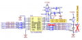
I am using TLC59208F LED Driver to driver LED.
Now i have confusion over RESET pin state in hardware.
RESET pin should needed pull up or pull down can anybody help me ?

Out is also active low - so i do not understand when LEDs will work ?

http://www.ti.com/lit/ds/symlink/tlc59208f.pdf

Thanks in Advance !!!
hello

the keyword is “connection”.

The reset pin requires a pull-up if:

1. if there is no connection ( the pin is not used).

2. if connected with an external RC POR circuit. This is inherent with an RC POR circuit (As mentioned by EricG)

The reset pin does not require a pull-up if:

3. connected to an active control output like an MCU.

hope that helps.

eT
 

Thread Starter

mishra87

Joined Jan 17, 2016
1,036
hello

the keyword is “connection”.

The reset pin requires a pull-up if:

1. if there is no connection ( the pin is not used).

2. if connected with an external RC POR circuit. This is inherent with an RC POR circuit (As mentioned by EricG)

The reset pin does not require a pull-up if:

3. connected to an active control output like an MCU.

hope that helps.

eT
Thanks both for information.
It's quite information.

Sorry for being childish and asking again question:

In case 3 : If reset is control by microcntroller reset pulse ....do we require any pull down resistor or any decopupling capacitor on reset pin...

As in evaluation board 1000pf capacitor used...

Somesomites i confused that active low reset means led driver only work when there is low signal seen at led driver reset pin ....

When reset pin is high led driver won't work and i am not sure if my understanding is correct ?
 

eetech00

Joined Jun 8, 2013
3,949
Thanks both for information.
It's quite information.

Sorry for being childish and asking again question:

In case 3 : If reset is control by microcntroller reset pulse ....do we require any pull down resistor or any decopupling capacitor on reset pin...

As in evaluation board 1000pf capacitor used...
You'll need to look at the rest of the external circuit connected to the Reset pin at J1. It very likely connects to a pull up resistor.
If the driver reset pin connects to an MCU I/O pin, and a "weak pullup" is available for the pin, then activate the weak pull up. Otherwise, it likely doesn't need one because the I/O pin is automatically pulled up or down depending on the output logic state.

Generally, a capacitor is only needed for an RC timer ( like used for POR) or for debouncing a mechanical switch used to reset the driver..

Somesomites i confused that active low reset means led driver only work when there is low signal seen at led driver reset pin ....
Active low is always (at least in my experience) in the context of the input pin function. This means that a logic low applied at the Reset pin will activate reset and reset the driver, causing the output to return to the default state. The default state is "Off" (LEDRx=00). The reset pin requires a voltage below 0.2v to activate reset. So the voltage at this pin needs to be higher then 0.2v for normal operation.

When reset pin is high led driver won't work and i am not sure if my understanding is correct ?
Then you have something else wrong. We need more specific information other than "it wont work".
What is not working?

eT
 
Last edited:
Top