Facebook
 Google
 GitHub
 Linkedin
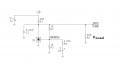
Hi,Hello , I need to tune my voltage around this value , for tuning I do need two resistors.did my currents in post 16 are ok ?
Thanks .
Do you mean you want to get -2.5v output?
If so, I believe you can connect the Vref pin directly ground but only in your negative output voltage circuit. That should give you -2.5 volts output as long as you have enough input voltage. You should also test with some load on the output also.
What current are you talking about, and where are you measuring it?
If you mean the cathode current that can be from 1ma to 100ma as per one of the data sheets.
Attachments
-
 50.6 KB Views: 8
Last edited: