Time step too small in LTSpice DAB simulation

Thread Starter

Circleplus7

Joined Aug 10, 2020
21
Hi

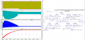
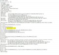
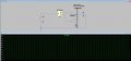
I made a DAB simulation with the existing MOSFET model. It is working. But now I want to use the actual primary MOSFET model(attached sct3160kl.lib) to replace the previous primary MOSFET in DAB simulation. Now I just add one Mosfet, it doesn't work because the time step is too small. I changed all the solver and try to add small resistance around the pulse, but it still doesn't work. I made a very simple circuit (attached Mosfet example. JPG) to verify the MOSFET model is correct. So I don't know how to solve this, maybe I can set a smaller minimum time step? but how can I set it? Is there anyone who can help me? Thanks so much.
 

Attachments

Alec_t

Joined Sep 17, 2013
14,313
Welcome to AAC!
Try editng the inductor properties by giving them a bit of series resistance or parallel capacitance.
 

ci139

Joined Jul 11, 2016
1,898
there might be 3 primary things that might be the cause of this
(1) no source stepping at startup = the DC op point may be way off actual with ideal Vs and Vgt
(2) your gate drive starts the 20ns rise with the simulation start (before the circuit settles)
(3) simulation minimum time-step should be at least ≤ 1/f. max or ≤ dt.min (e.g. in your case 10ns) to get the "accurate" simulation result for
try Vgt initial delay ≥ 20µs & the Vs gradual stepping at startup
 

Thread Starter

Circleplus7

Joined Aug 10, 2020
21
there might be 3 primary things that might be the cause of this
(1) no source stepping at startup = the DC op point may be way off actual with ideal Vs and Vgt
(2) your gate drive starts the 20ns rise with the simulation start (before the circuit settles)
(3) simulation minimum time-step should be at least ≤ 1/f. max or ≤ dt.min (e.g. in your case 10ns) to get the "accurate" simulation result for
try Vgt initial delay ≥ 20µs & the Vs gradual stepping at startup
Sorry, I cannot understand what you mean. for (1), do you mean I need to give a step DC voltage as the source in the beginning? for (2), do you mean I need to give a ramp to gate pulse start? for (3), could you give me a more detailed explanation? Thanks so much
 

Thread Starter

Circleplus7

Joined Aug 10, 2020
21
Thanks for your correction. Now my simulation works. I also change the secondary MOSFET, I would like to ask why you add the option command. You change the default value of the trtol, the abstol, the gshunt, and the cshunt, why? Do you change the minimum time step through changing accuracy? Now my simulation time is so long, could I shorten the time through changing the accuracy?

Thanks for your answer.
 

Bordodynov

Joined May 20, 2015
3,179
To speed up the calculations, you can increase the maximum step in the Tran team. You can also increase the value of Trtol. For acceleration you can use .Save . Using this command can greatly reduce the amount of memorable information and reduce the time it takes to write a raw-file to disk.
I have applied other options to improve convergence and speed up the account.
 

ci139

Joined Jul 11, 2016
1,898
? it throws the instability randomly around . . . i tried to patch such step by step until below (not my model - won't test around with)
DAB_0728_1 - modified.png
 

Thread Starter

Circleplus7

Joined Aug 10, 2020
21
To speed up the calculations, you can increase the maximum step in the Tran team. You can also increase the value of Trtol. For acceleration you can use .Save . Using this command can greatly reduce the amount of memorable information and reduce the time it takes to write a raw-file to disk.
I have applied other options to improve convergence and speed up the account.
Thanks for your answer, it is very useful. However, if I increase the trtol, my simulation will have less accuracy. Actually my secondary side of DAB circuit need 24 Mosfet (6 for parallel), when I add these command, the accuracy is terrible now.
 

Thread Starter

Circleplus7

Joined Aug 10, 2020
21
Thanks for your answer, it is very useful. However, if I increase the trtol, my simulation will have less accuracy. Actually my secondary side of DAB circuit need 24 Mosfet (6 for parallel), when I add these command, the accuracy is terrible now.
I think my waveform is terrible is not because of these commands. as long as I parallel the MOSFET on the secondary side, the output voltage will be much lower than normal. It is wired, My MOSFET spice model was downloaded from the manufacturer website, the internal resistance should be very low, it shouldn't be any difference if I parallel it or not. Do you have similar experience?
 

Bordodynov

Joined May 20, 2015
3,179
See.
I corrected the transistor model for LTspice. Its difference is that the default inductance has a serial resistance of 1 mOhm (I did Rser=0). I also corrected the parallel resistance of the inductance. I was the first to apply the parallel inductance resistor to the leads. Typical inductances are 4 -7nH and I thought it was normal to use 10 ohms. Many had problems with convergence and counting time and I added this resistor to solve the problems. Apparently, my discussions with LTspice users and solutions were seen by the developers of factory models and adopted my experience. I offered my solution for a year and then found it in other models. But 10 Ohm is good for inductances of about 5nH. At 1nH, you need 2 ohms. Without these parallel resistors, the parasitic inductances of the transistor leads had very high quality, and this caused fluctuations at a frequency of about 1GHz, which affected the convergence and counting time.
 

Attachments

Thread Starter

Circleplus7

Joined Aug 10, 2020
21
See.
I corrected the transistor model for LTspice. Its difference is that the default inductance has a serial resistance of 1 mOhm (I did Rser=0). I also corrected the parallel resistance of the inductance. I was the first to apply the parallel inductance resistor to the leads. Typical inductances are 4 -7nH and I thought it was normal to use 10 ohms. Many had problems with convergence and counting time and I added this resistor to solve the problems. Apparently, my discussions with LTspice users and solutions were seen by the developers of factory models and adopted my experience. I offered my solution for a year and then found it in other models. But 10 Ohm is good for inductances of about 5nH. At 1nH, you need 2 ohms. Without these parallel resistors, the parasitic inductances of the transistor leads had very high quality, and this caused fluctuations at a frequency of about 1GHz, which affected the convergence and counting time.
Thanks for your patient explanation.

I learned a lot and my simulation is perfect now. When I parallel 6 secondary MOSFETs, it keeps the same. But I have one more question. My secondary MOSFET spice model's .lib document is shown in fig.2. it has a different format from fig.1. It has three inductors, Ld, Lg, Ls. I would like to know if I want to correct this MOSFET model(fig.2) according to your method, which inductor (Ld? Ls? Lg? or all of them?) should be added by Rser and Rpar? I tried to add Rser and Rpar separately and together for these three inductors to see if there is any difference, but there is no difference in the output voltage. So could you explain more about how and why to add the Rser and Rpar in MOSFET? I also attached the .lib document(IPP023N10N5_L0).

Thanks so much for your time.
 

Attachments

Bordodynov

Joined May 20, 2015
3,179
You did the right thing. Transistor models are made for Spice simulators, and they have no built-in serial resistance. The influence of setting Rser=0 is determined by the channel resistance. With an open channel resistance of 160 mOhm, the effect is small. But there are models of transistors which have Ron=1-5mOhm. And for such a case, 2mOhm will greatly affect the result. Adding Rpar improves the convergence of the calculation and reduces the calculation time. The inductance resistance of 1nH is 2Ohm at 318MegHz. For frequencies lower than this value, the additional resistance has little effect. The creator of LTspice in his model VDMOS generally ignored the parasitic inductances of the transistor terminals. This introduces error, but speeds up counting and improves convergence. IRF transistor models also without inductances.
If you see Ls and Ld inductance models, I recommend adding Rser=0. This is especially important for low impedance transistors with open channel. This is necessary. In LTspice, in the settings menu (hammer), you have the option of setting inductances for which you have not set Rser=0 to Rser. But in some schemes the default value Rser=1mOhm is useful.
 
Last edited:

Thread Starter

Circleplus7

Joined Aug 10, 2020
21
You did the right thing. Transistor models are made for Spice simulators, and they have no built-in serial resistance. The influence of setting Rser=0 is determined by the channel resistance. With an open channel resistance of 160 mOhm, the effect is small. But there are models of transistors which have Ron=1-5mOhm. And for such a case, 2mOhm will greatly affect the result. Adding Rpar improves the convergence of the calculation and reduces the calculation time. The inductance resistance of 1nH is 2Ohm at 318MegHz. For frequencies lower than this value, the additional resistance has little effect. The creator of LTspice in his model VDMOS generally ignored the parasitic inductances of the transistor terminals. This introduces error, but speeds up counting and improves convergence. IRF transistor models also without inductances.
If you see Ls and Ld inductance models, I recommend adding Rser=0. This is especially important for low impedance transistors with open channel. This is necessary. In LTspice, in the settings menu (hammer), you have the option of setting inductances for which you have not set Rser=0 to Rser. But in some schemes the default value Rser=1mOhm is useful.
Thanks for your answer. You are very professional!
 

Thread Starter

Circleplus7

Joined Aug 10, 2020
21
You did the right thing. Transistor models are made for Spice simulators, and they have no built-in serial resistance. The influence of setting Rser=0 is determined by the channel resistance. With an open channel resistance of 160 mOhm, the effect is small. But there are models of transistors which have Ron=1-5mOhm. And for such a case, 2mOhm will greatly affect the result. Adding Rpar improves the convergence of the calculation and reduces the calculation time. The inductance resistance of 1nH is 2Ohm at 318MegHz. For frequencies lower than this value, the additional resistance has little effect. The creator of LTspice in his model VDMOS generally ignored the parasitic inductances of the transistor terminals. This introduces error, but speeds up counting and improves convergence. IRF transistor models also without inductances.
If you see Ls and Ld inductance models, I recommend adding Rser=0. This is especially important for low impedance transistors with open channel. This is necessary. In LTspice, in the settings menu (hammer), you have the option of setting inductances for which you have not set Rser=0 to Rser. But in some schemes the default value Rser=1mOhm is useful.

Hi, I hope you are doing well.
I have one more question about how to revise the parameter in the MOSFET spice in LTSpice. I would like to compare the efficiency with different gate resistance. in default Rg value the Rg is 1.3 (type value in the datasheet), we consider external gate resistance in the lab. so we want to test efficiency with Rg=3.6 ohm (considering external gate resistance for turning on) and Rg=2 ohm for turning off. so I don't know how to make the Rg is different when turns on and off. Now I think Rg=3.6 ohm is the same when turns on and off.
Do you have a similar experience with that? Thank you so much.
IPP023N10N5.JPG
 

Bordodynov

Joined May 20, 2015
3,179
First of all, you commented out my additive inductance parameters in vain. The standard value of Rser=1m. The original transistor model is not designed for LTspice. By changing my model, you have increased the resistance of the transistor by 1 mOhm. I added the Rpar parameters for convergence and to increase the counting speed. By the way, in the new models the model developers used my idea (parallel resistors to inductors).
Second. Your problem is easily solved. You have to put a diode in series with the gate.
Diode model:
.model Dg d vfwd=0 Ron=0.7 Roff=2.3
I think you can guess how to turn on the diode. The resistance values can also be negative. I have a question: do you simulate a source with these parameters?
 

Thread Starter

Circleplus7

Joined Aug 10, 2020
21
First of all, you commented out my additive inductance parameters in vain. The standard value of Rser=1m. The original transistor model is not designed for LTspice. By changing my model, you have increased the resistance of the transistor by 1 mOhm. I added the Rpar parameters for convergence and to increase the counting speed. By the way, in the new models the model developers used my idea (parallel resistors to inductors).
Second. Your problem is easily solved. You have to put a diode in series with the gate.
Diode model:
.model Dg d vfwd=0 Ron=0.7 Roff=2.3
I think you can guess how to turn on the diode. The resistance values can also be negative. I have a question: do you simulate a source with these parameters?
Thank you for your explanation. You mean that connecting a diode in series with the gate is in the spice model or just adding resistance and connecting a diode in the simulation file? For your question, yes we are working on a low voltage supply. We hope to get a more accurate model to compare it with the experiment.
 

Bordodynov

Joined May 20, 2015
3,179
You can do different things. I gave you an idea of how to make a diode into a resistor with different resistance for different current directions. I am not sure about your concept of redesigning the model. The impedance of the source can be different depending on the direction of the current (e.g. the output resistance of the gate driver) and this fact must be taken into account. You didn't report anything about the source impedance.
 

Thread Starter

Circleplus7

Joined Aug 10, 2020
21
You can do different things. I gave you an idea of how to make a diode into a resistor with different resistance for different current directions. I am not sure about your concept of redesigning the model. The impedance of the source can be different depending on the direction of the current (e.g. the output resistance of the gate driver) and this fact must be taken into account. You didn't report anything about the source impedance.
I will think of that. Thank you so much.
 
Top