This circuit has floating nodes in LT Spice?

Status
Not open for further replies.

Thread Starter

Allenph

Joined May 27, 2015
76

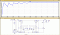
This is the circuit I'm working on. This circuit probably doesn't work as intended to begin with, but that's not the point.

LT Spice keeps complaining that it doesn't have a reference to ground. I get an error that says "This circuit has floating nodes."

I found <a href="http://electronics.stackexchange.com/questions/144792/how-to-resolve-floating-node-error-in-pspice">this</a> but that didn't solve my problem.

It would be one thing to just connect a ground somewhere, but that will ruin the validity of my circuit.

The voltage source defined as MAINS in this circuit is just that...a simulation of the mains. It is a 60Hz sine wave with an amplitude of 120V. If I add a ground to it, I won't get the negative part of my wave!

The resistor connected to the voltage source is there to prevent another error being thrown about having inductors in parallel with the voltage source.

How can I keep this circuit equivalent to the real world so that I can simulate without losing half my wave from my MAINS voltage source?
 

WBahn

Joined Mar 31, 2012
29,976
The simulator has to have a reference node, but there is nothing that says that that says that the voltages in the system can't go positive and negative relative to that reference.

You can pick any node you want as your reference. That's all it is ... a reference. The obvious choice is the bottom rail in your schematic.

You may need to refer the circuit on the primary side of your transformer as well, but if you do you can use a high valued resistor. The simulator just needs a DC path in order to converge.
 

Thread Starter

Allenph

Joined May 27, 2015
76
Hi,
It runs OK for me with the 'Gnd' ref node as shown.
I have replaced the diodes with one I have on my list.
I ended up doing something almost exactly the same.

I don't know how you got it to start without the resistor on the primary coil though.
 

ericgibbs

Joined Jan 29, 2010
18,766
If your local mains supply is say stated as 120V 60Hz, it means its 120V RMS.
The actual peak voltage of the 120V RMS is 1.414 *120V = ~169V.

This is the peak voltage applied to the input to the full wave rectifier diode bridge, which means the capacitor C1 will charge to close to 169V DC [ there are diode voltage drops, say 1.4V total] so thats around ~167.5V !!!

This will of course be applied to the Load via the circuit.

OK.
 

Thread Starter

Allenph

Joined May 27, 2015
76
If your local mains supply is say stated as 120V 60Hz, it means its 120V RMS.
The actual peak voltage of the 120V RMS is 1.414 *120V = ~169V.

This is the peak voltage applied to the input to the full wave rectifier diode bridge, which means the capacitor C1 will charge to close to 169V DC [ there are diode voltage drops, say 1.4V total] so thats around ~167.5V !!!

This will of course be applied to the Load via the circuit.

OK.
That's definitely good to know. It will effect my transformer. But, that's all that will change...the transformer. At least I think?

Where did you get that 1.414?
 

ericgibbs

Joined Jan 29, 2010
18,766
Again, 12V would be considered a RMS value, so the peak would be approx 17V [ less two diode drops after the rectifier] ie: ~ 15.5Vdc

I would use 10H for the transformer primary and 100mH for the secondary, thats a 10:1 step down, also set the voltage to 169V for the mains.

Is the load only a 10K resistance.?
 

Thread Starter

Allenph

Joined May 27, 2015
76
Again, 12V would be considered a RMS value, so the peak would be approx 17V [ less two diode drops after the rectifier] ie: ~ 15.5Vdc

I would use 10H for the transformer primary and 100mH for the secondary, thats a 10:1 step down, also set the voltage to 169V for the mains.

Is the load only a 10K resistance.?
No, that's just a dummy load. The resistance of my control electronics will be changing that's why I went with the buck converter. Let me see if I can come up with a formula to get the peak voltage I want. Should be just some Algebra.
 

Thread Starter

Allenph

Joined May 27, 2015
76
Again, 12V would be considered a RMS value, so the peak would be approx 17V [ less two diode drops after the rectifier] ie: ~ 15.5Vdc

I would use 10H for the transformer primary and 100mH for the secondary, thats a 10:1 step down, also set the voltage to 169V for the mains.

Is the load only a 10K resistance.?
So about 14:1 will give me my peak 12V that I want.
 

MrAl

Joined Jun 17, 2014
11,389
Hi,

1.4142 is the square root of 2, often written as sqrt(2).
That is the ratio of the Peak voltage to RMS voltage of a sine wave.
So if your RMS voltage is 120v, the peak is 120*1.4142=169.7 volts, which is the highest point on the sine wave.
A more accurate calculation is:
sqrt(2)=1.4142135623730950488016887242097
120*sqrt(2)=169.70562748477140585620264690516

If you already know the peak value and you want to know what the RMS value is, just divide by the sqrt(2).

All of the above only holds true for a sine wave however.
 
Status
Not open for further replies.
Top