Facebook
 Google
 GitHub
 Linkedin
My sister-in-law asked me to look at a set of Christmas lights - the type with LEDs wired with alternate polarity allowing a variety of flashing patterns. One of the kids had run over the wire between the controller and the first LED with an electric scooter causing it to get snagged in the wheel and break. But on examination, it wasn't just a question of repairing a broken wire - it looked like it'd shorted out, damaging the controller.
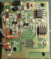
I had to cut open the controller with a dremel, but inside, it seemed fairly simple: an H-bridge driving the LED string with either polarity, and controlled by a microcontroller with attached serial NVRAM. The H-bridge uses 6 SOT transistors, 4 of which were dead (testing the B-E and B-C junctions with a multimeter on the diode range). The circuit wasn't hard to trace (or so it seemed), but the circuit I came up with couldn't possibly work. Clearly something wrong either with my tracing or with the component identification. Here's a photo of the board and my attempt to trace the circuit:


I've marked the inputs from the microcontroller IN1 and IN2 (presumably 5V logic levels), and the outputs to the LED string OUT1 ad OUT2. The supply is 31V.
I could understand the circuit if Q3 and Q4 were PNP and the emiter and collector reversed, but with the red testmeter lead on the pin 1 (base) they give around 0.7V on diode test on the other two pins. (These are the only 2 out of the 6 trasistors to have survived.) The abbreviated marking J6 appears most plausibly to be NPN trasistor S9014.
The flaw in my logic is escaping me, perhaps partly due to a brain befuddled by an excess of turkey and Christmas pudding. Can someone please point out my silly mistake?
I had to cut open the controller with a dremel, but inside, it seemed fairly simple: an H-bridge driving the LED string with either polarity, and controlled by a microcontroller with attached serial NVRAM. The H-bridge uses 6 SOT transistors, 4 of which were dead (testing the B-E and B-C junctions with a multimeter on the diode range). The circuit wasn't hard to trace (or so it seemed), but the circuit I came up with couldn't possibly work. Clearly something wrong either with my tracing or with the component identification. Here's a photo of the board and my attempt to trace the circuit:
I've marked the inputs from the microcontroller IN1 and IN2 (presumably 5V logic levels), and the outputs to the LED string OUT1 ad OUT2. The supply is 31V.
I could understand the circuit if Q3 and Q4 were PNP and the emiter and collector reversed, but with the red testmeter lead on the pin 1 (base) they give around 0.7V on diode test on the other two pins. (These are the only 2 out of the 6 trasistors to have survived.) The abbreviated marking J6 appears most plausibly to be NPN trasistor S9014.
The flaw in my logic is escaping me, perhaps partly due to a brain befuddled by an excess of turkey and Christmas pudding. Can someone please point out my silly mistake?